The presented 3 phase VFD circuit (designed by me) can be used for controlling the speed of any three phase brushed AC motor or even a brushless AC motor. The idea was requested by Mr. Tom
Using the VFD
The proposed 3-phase VFD circuit can be universally applied for most 3-phase AC motors where the regulation efficiency is not too critical.
It can be specifically used for controlling squirrel cage induction motor speed with an open loop mode, and possibly also in the closed loop mode which will be discussed in the later part of the article.
Modules Required for 3 Phase Inverter
For designing the proposed 3 phase VFD or variable frequency drive circuit the following fundamental circuit stages are essentially required:
- PWM voltage controller circuit
- 3 phase high side/low side H-bridge driver circuit
- 3 Phase generator circuit
- Voltage to frequency converter circuit for generating V/Hz parameter.
I have explained the functioning details of the above stages with the help of the following explanation:
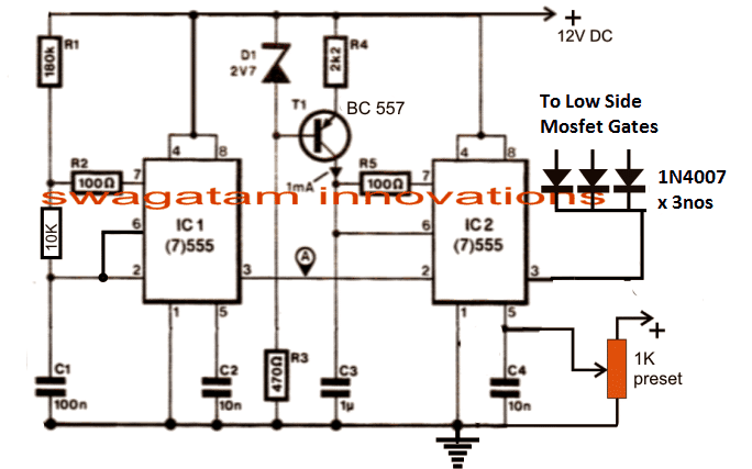
A simple PWM voltage controller circuit can be witnessed in the diagram given below:
The PWM Controller
I have already incorporated and explained the functioning of the above PWM generator stage which is basically designed for generating a varying PWM output across pin3 of IC2 in response to the potential applied at pin5 of the same IC.
The 1K preset shown in the diagram is the RMS control knob, which may be appropriately adjusted for acquiring the desired proportionate amount of output voltage in the form of PWMs at pin3 of IC2 for further processing. This is set to produce a corresponding output that may be equivalent to the mains 220V or 120V AC RMS.
The H-Bridge Driver Circuit
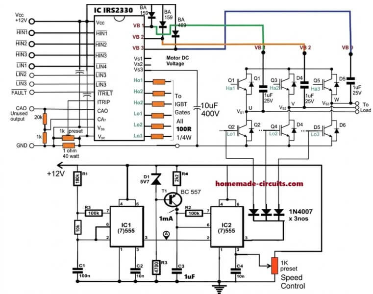
The next diagram below shows a single chip H-bridge 3 phase driver circuit using the IC IRS2330.
The design looks straightforward as most of the complexities are handled by the chips in-built sophisticated circuitry.
A well calculated 3 phase signal is applied across the HIN1/2/3 and LIN1/2/3 inputs of the IC through a 3 phase signal generator stage.
The outputs of the IC IRS2330 can be seen integrated with 6 mosfets or IGBTs bridge network, whose drains are appropriately configured with the motor which needs to be controlled.
The low side mosfet/IGBT gates are integrated with the IC2 pin#3 of the above discussed PWM generator circuit stage for initiating the PWM injection into the bridge mosfet stage. This regulation ultimately helps the motor to gain the desired speed as per the settings (via the 1 k preset in the first diagram).
In the following diagram we visualize the required 3 phase signal generator circuit.
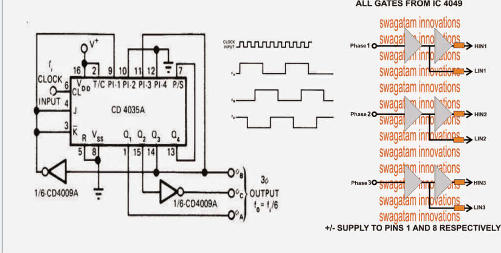
Configuring the 3-Phase Generator Circuit
The 3 phase generator is constructed around a couple of CMOS chips CD4035 and CD4009 which generates accurately dimensioned 3 phase signals across the shown pinouts.
The frequency of the 3 phase signals depends on the fed input clocks which should be 6 times the intended 3 phase signal. Meaning, if the required 3 phase frequency is 50 Hz, the input clock should be 50 x 6 = 300 Hz.
It also implies that the above clocks could be varied in order to vary the effective frequency of the driver IC which in turn would be responsible of varying the motor operational frequency.
However since the above frequency alteration needs to be automatic in response to the varying voltage, a voltage to frequency converter becomes essential. The next stage discusses a simple accurate voltage to frequency converter circuit for the required implementation.
How to Create a Constant V/F Ratio
Typically in induction motors, in order to maintain an optimal efficiency of the motor speed and toque, the slip speed or the rotor speed needs to be controlled which in turn becomes possible by maintaining a constant V/Hz ratio. Since the stator magnetic flux is always constant regardless of the input supply frequency, the rotor speed becomes easily controllable by maintaining the V/Hz ratio constant.
In an open loop mode, this can be done roughly by maintaining predetermined V/Hz ratios, and implementing it manually. For example in the first diagram this may be done by suitably adjusting the R1 and the 1K preset. R1 determines the frequency and the 1K adjusts the RMS of the output, therefore by suitably adjusting the two parameters we can enforce the required amount V/Hz manually.
However to get a relatively accurate control of an induction motor torque and speed, we have to implement a closed loop strategy, wherein the slip speed data needs to be fed to the processing circuit for an automatic adjustment of the V/Hz ratio so that this value always remains near about constant.
Implementing the Closed Loop Feedback
The first diagram on this page can be suitably modified for designing the closed loop automatic V/Hz regulation as shown below:
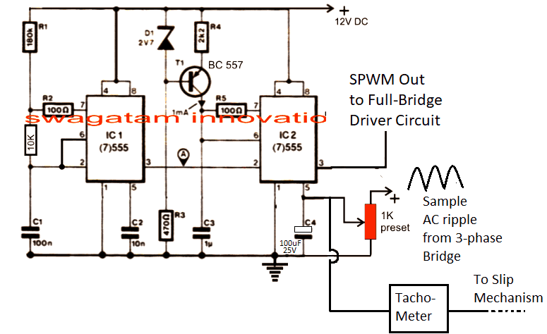
In the above figure, the potential at pin#5 of IC2 determines the width of the SPWM which is generated at pin#3 of the same IC. The SPWM are generated by comparing the mains 12V ripple sample at pin#5 with triangle wave at pin#7 of IC2, and this is fed to the low side mosfets for the motor control.
Initially this SPWM is set at some adjusted level (using 1K perset) which triggers the low side IGBT gates of the 3-phase bridge for initiating the rotor movement at the specified nominal speed level.
As soon the rotor rotor begins rotating, the attached tachometer with the rotor mechanism causes an proportional additional amount of voltage to develop at pin#5 of IC2, this proportionately causes the SPWMs to get wider causing more voltage to the stator coils of the motor. This causes further increase in the rotor speed causing more voltage at pin#5 of IC2, and this goes on until the SPWM equivalent voltage is no longer able to increase and the stator rotor synchronization attains a steady-state.
The above procedure goes on self adjusting throughout the operational periods of the motor.
How to Make and Integrate the Tachometer
A simple tachometer design can be seen in the following diagram, this could be integrated with the rotor mechanism such the rotational frequency is able to feed the base of the BC547.
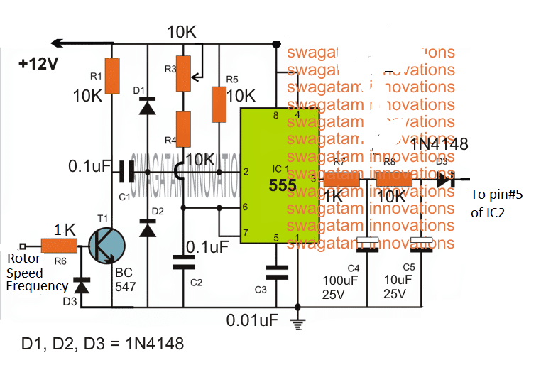
Here the rotor speed data is collected from a hall effect sensor or a IR LED/Sensor network and is fed to the base of T1.
T1 oscillates at this frequency and activates the tachometer circuit made by appropriately configuring an IC 555 monostable circuit.
The output from the above tachometer varies proportionately in response to the input frequency at the base of T1.
As the frequency rises the voltage at the extreme right side D3 output also rises and vice versa, and helps to keep the V/Hz ratio to a relatively constant level.
How to Control Speed
The speed of motor using constant V/F can be achieved by altering the frequency input at the clock input of IC 4035. This can be achieved by feeding a variable frequency from a IC 555 astable circuit or any standard astable circuit to the clock input of IC 4035.
Changing the frequency effectively changes the operating frequency of the motor which correspondingly lowers the slip speed.
This is detected by the tachometer, and the tachometer proportionately reduces the potential at pin#5 of the IC2 which in turn proportionately reduces the SPWM content on the motor, and consequently the voltage for the motor is reduced, ensuring motor speed variation with the correct required V/F ratio.
A Homemade V to F Converter
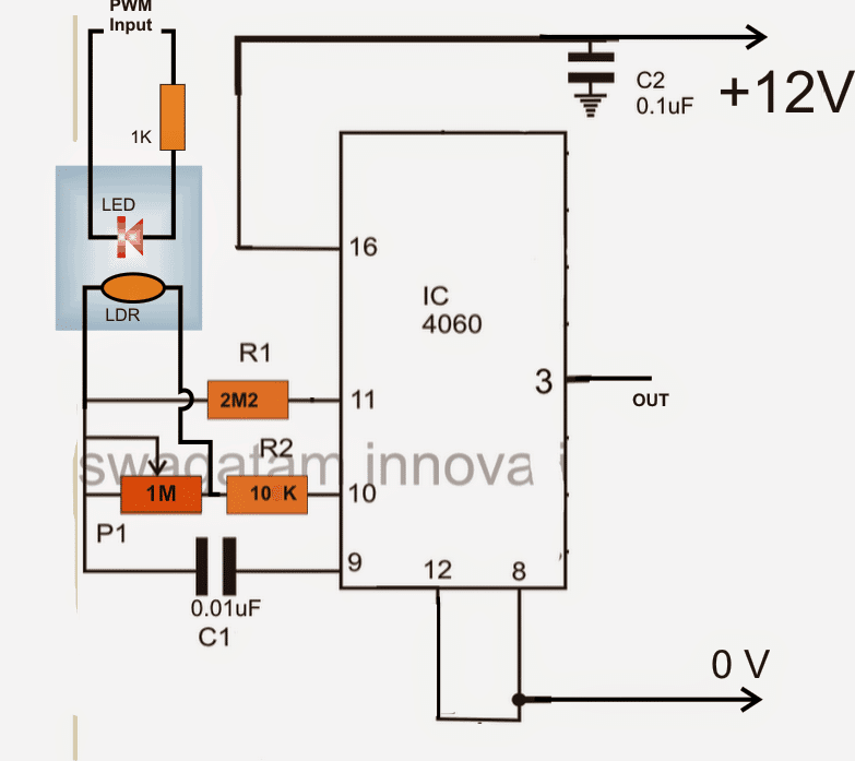
In the above voltage to frequency converter circuit a IC 4060 is used and its frequency dependent resistance is influenced through a LED/LDR assembly for the intended conversions.
The LED/LDR assembly is sealed inside a light proof box, and the LDR is positioned across a 1M frequency dependent resistor of the IC.
Since the LDR/LDR response is fairly linear, the varying illumination of the LED on the LDR generates a proportionately varying (increasing or decreasing) frequency across pin3 of the IC.
The FSD or the V/Hz range of the stage could be set by appropriately setting up the 1M resistor or even the C1 value.
The LED is voltage is derived and illuminated through the PWMs from the first PWM circuit stage. It implies that as the PWMs vary, the LED illumination will also vary which in turn would give rise to a proportionately increasing or decreasing frequency at pin3 of the IC 4060 in the above diagram.
Integrating the Converter with VFD
This varying frequency from the IC 4060 now simply needs to be integrated with the 3 phase generator IC CD4035 clock input.
The above stages form the main ingredients for making a 3 phase VFD circuit.
Now, it would be important to discuss regarding the DC BUS required for supplying the IGBT motor controllers and the setting up procedures for the entire design.
The DC BUS applied across the IGBT H-bridge rails may be obtained by rectifying the available 3 phase mains input using the following circuit configuration. The IGBT DC BUS rails are connected across the points indicated as "load"
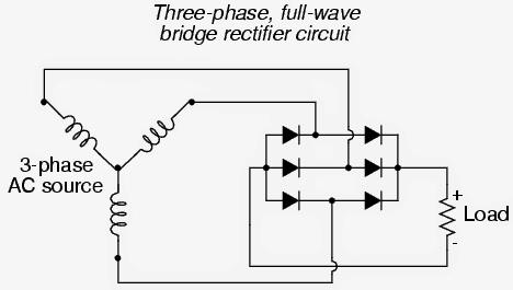
For a single phase source the rectification may be implemented using standard 4 diode bridge network configuration.
How to Set Up the proposed 3 phase VFD circuit
It may be done as per the following instructions:
After applying the DC bus voltage across the IGBTs (without the motor connected) adjust the PWM 1k preset until the voltage across the rails become equal to the intended motor voltage specs.
Next adjust the IC 4060 1M preset in order to adjust any of IC IRS2330 inputs to the required correct frequency level as per the given motor specifications.
After the above procedures are completed, the specified motor may be connected and supplied with different voltage levels, V/Hz parameter and confirmed for an automatic V/Hz operations over the connected motor.




Questions & Answers
اريد صورة لكامل المشروع تجمع الدخل ودائرة التحكم والخرج في صورة واحدة
hello
good day
we are developing testing proposes in house used, IGBT base three phase regulator ,
1700 Voltage, 500amp
guided us controller and IGBT
Hi, do you want it to be an Arduino based design, or just an analogue version??
Dynamic Braking Resistor (DBR) or Dynamic Braking Unit (DBU) is an essential electrical component used in various industrial applications to safely dissipate extra energy produced when an electric motor or other devices are braking. When a motor slows down or stops, it behaves like a generator, creating a reverse electrical current called back electromotive force (EMF). If this energy isn’t managed properly, it could cause damage to both the motor and the connected drive system.
To handle this excess energy, dynamic braking is used in systems like elevators, cranes, electric trains, and vehicles—basically any equipment that requires frequent, controlled slowing down or stopping. In most setups, the DBR works alongside a Variable Frequency Drive (VFD), which is a motor-controlling system that helps regulate this braking process. In this guide, we’ll walk through how to connect a Dynamic Braking Resistor to a VFD.
Step-by-Step Connection Guide
Identify the DBR Terminals in the VFD:
Most VFDs come with specific terminals dedicated to connecting a DBR. Typically, there are two terminals, one for the positive connection and another for the negative. These terminals are usually labeled “+” and “-” or more commonly as “DC+” and “DC-”. In the wiring diagram provided, you’ll see that the VFD has clearly marked “DC+” and “DC-” terminals.
Connect the Input of the DBR to the VFD:
You’ll then connect one terminal of the DBR to the “DC+” terminal on the VFD and the other DBR terminal to the “DC-” on the VFD. This setup allows the DBR to absorb the extra energy generated by the motor while braking.
Consider a Resistor Contactor or Brake Chopper:
In some VFD setups, you might need an additional component like a resistor contactor or brake chopper to control how the DBR is connected to the VFD. A brake chopper is a solid-state device that regulates the flow of energy between the VFD and the DBR. If your system includes one, make sure to follow the manufacturer’s directions for proper installation.
Configure the VFD’s Parameters:
To enable the DBR to function properly, you’ll need to adjust some settings on the VFD. This might include turning on dynamic braking mode, entering the correct resistance value of the braking resistor, and configuring torque or current limits. These settings vary depending on the model of your VFD and the specific needs of your application.
Always follow the manufacturer’s instructions for both the VFD and DBR when making connections and adjusting parameters. Incorrect setup or misconfigured parameters can result in system errors or even damage the equipment. Consulting the user manuals is highly recommended.
How Dynamic Braking Works
When the motor is slowing down or stopping, the VFD senses this and switches to dynamic braking mode. Instead of just cutting power to the motor (as in normal stopping), the VFD directs the surplus energy generated during braking to the DBR.
In this system, the DBR is connected in parallel with the VFD’s DC bus and acts as a load that absorbs this excess energy. The DBR has a high-power rating and specific resistance designed to convert the energy into heat safely.
Because dissipating energy in the form of heat can cause the DBR to overheat, they are usually equipped with cooling systems like heatsinks or fans to keep the temperature down.
Once the braking process is complete, the VFD switches back to its normal mode, resuming its role of supplying the right amount of voltage and frequency to the motor for smooth operation.
In summary, a DBR ensures that the energy generated when slowing down a motor is safely and efficiently managed, preventing damage to the motor and other electrical components.
Thank you Jitu,
you can try the following circuit:
Sir, Namaskar.
I am technician
I won’t full circuit diagram of DBU
(DYNAMIC BRAKING UNIT ) & DBR for three phase motor.
My email : jvpateljv@gmail.com
Thank you.
Hi Jitu,
Can you please provide more details on how dynamic braking is supposed to work, about its working concept?
I will try to figure it out…
Dear Sir
IC IRS2330 is not available in Sri Lanka. Is it available in India. Otherwise manufacturers sells it in large quantities only.
Grateful for your help and guidance.
Regards
Pradeep
Thank you Pradeep,
The IC is available in India, or you can also try getting it from popular online stores like amazon or Ebay.
Dear Sir, what is the recommended IGBT for 110VX3 phase motor? Can we use IXSK 80N60B for this? Grateful for your advice.
Hello Pradeep, can you please provide the power rating (wattage) of the motor, I will try to figure it out…
Could you provide me a complete (composite) and clear diagram for the circuit.
The full diagram can be too large to fit on the screen, therefore I have shown the stages separately.
Do you have the circuit board & components for this as DIY project?
Sorry, PCB is not available for this project.
Hi Sir,
My circuit is almost completed earlier but due to my father’s cervical spine surgery I unable to take field trial bcz without his help and guidance it is risky (it is High voltage and high current power supply).
Now he is comfortable to do this.We will be planned it in this week.
after taking the same testing I will be shared all details to you.
I have required a information before it about heat sink. If I connected 5HP 3 phase submersible motor to the circuit load which heat sink I should be required?
Thank you Sanika, for updating the information!
Glad to know your father has recovered from the illness and is doing good.
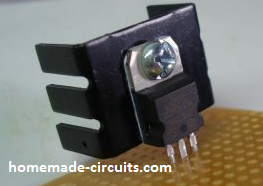
Regarding the heatsink, it can be difficult to assume how large the heatsink should be. It can be verified only though some practical testing. Initially you can use a medium sized finned type heatsink and check whether it gets too hot or not. If it gets too hot you may have to increase the size and so on.