In this post I have explained a simple ATX UPS circuit with an automatic charger for enabling an automatic changeover from mains to battery power during mains failures and for ensuring an uninterruptible operation of the ATX load.
Technical Specifications
I´m interested in your site and there are a lot good ideas. But for my actual idea I can´t find any solution and it´s driving me crazy. I want to make a ATX power supply with integrated UPS.
The idea is, to put a 230 to 19V power supply, a Li-Ion battery charger, a Li-Ion battery pack and a step-down converter for a picoPSU into a ATX power supply case.
The PicoPSU would be plugged outside of the case into a ATX connector, because the case is modular, also for the cables. So I´ve finished the board for all external connections (see attachment).
So, I need a two way power supply with 19V for the battery charger and 12V for the PicoPSU. The battery charger should be able to charge 4 or 8 batteries, 4 in a row and as an extension a pack of 4 parallel.
The voltage of the battery pack must be step down to 12V for the PicoPSU. Between those two 12V sources there must be a UPS function. Transistor or relay, doesn´t matter. The PicoPSU can be a up to 160 watts type.
My problems are the charger and the UPS function. Maybe you´re having an idea for a complete solution.
Thanks a lot
The Design
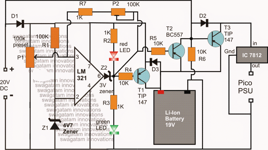
The requested ATX UPS circuit with charger can be implemented by using the above shown circuit, the details may be understood with the help of the following explanation:
The IC LM321 forms a standard comparator circuit stage and is positioned to monitor the battery voltage level and manage the cut-off actions for the set over-charge and low-charge thresholds appropriately.
The 20V input is obtained from a standard 20V/5amp AC to DC SMPS circuit, and the voltage is used for charging the attached 19V Li-ion battery via the LM321 charger controller circuit.
As long as this input is present, the battery is charged through T1, and when a full charge is reached, the opamp pin3 goes higher than its pin2 reference value (as preset by the pin3 100K resistor), illuminating the green LED and shutting off the red LED.
This prompts the output pin#6 to go high, disabling T1, which in turn cuts off the supply to the battery, preventing over charging of the battery.
Simultaneously. the 20V DC supply also finds its way to the Pico power supply unit via a dropping 12V regulator using the IC 7812.
The 20V supply input additionally used for keeping T3 disabled so that while the mains input is available, the battery voltage is unable to reach the Pico PSU
Now in an event when mains fails, the 20V input becomes eliminated and T3 is enabled to conduct.
The battery voltage is now instantly replaced for the mains input so that the pico power supply is able to get the supply without an interruption, or in other words, T3 executes the uninterruptible power supply action by quickly changing-over the supply from the mains to battery for the load each time mains power is disrupted.
During the mains failure, battery power is consumed by the load which causes the battery voltage to drop with time, and when it reaches the lower threshold (set by P2), the opamp output reverts to a low or a 0 volt.
This 0 volt also triggers the transistor T2 causing a positive potential is passed through its collector to the base of T3. This instantly disables T3 executing a low voltage cut off action and ensuring that no further power lose is caused for the battery, and a good battery condition is maintained throughout the ATX UPS operations.

Questions & Answers
Hi! What is the Inverting input and Non-Inverting Input pin number according to your schematic? Thanks a lot!
Hi, pin3 is non-inverting, pin2 is inverting
I was wondering if i was using the device while it is attached to an external power source wold the load be shifted from the batteries to the external power source.
and i have a question so i want to power a portable device. The device runs on a 16v lithium ion battery pack that has a built in BMS
that device draws 8 amps of power.
I want to charge the battery pack and use the device at the same time with a external power source.
how does one shift the load so that the device does not draw from the battery while charging.
The eternal power supply outputs 12v at 10A
i been at it for mouths
only clue i found was a load switch
I think you refer to this article, you might find it useful:
https://www.homemade-circuits.com/simple-dc-ups-circuit-for-modemrouter/
thank you
Hi Swagat,
I have been reading the circuits on your innovative websites and how it helps even for non technical getting interested in DIY.
I have seen some of the circuits you have proposed for UPS. I am looking for a very small ups to power my router for a very short time, lets say max 5 mins backup. This is a general problem of those living in apartments where backups are there but need few mins for generators to turn the power on.
I would like to use a laptop charger of 19.5 V, 3.5 A for powering my 12V, 1.5A router and using some chargeable batteries to provide the gap inputs when the power is gone. Can you help come up with some circuit with batteries overcharge protection as well?
Many Thanks
Hi Lakshya, thank you for liking my website, I appreciate your participation and interest very much…
did you investigate the following concept, you can easily build this and use it for your specific need
https://www.homemade-circuits.com/simple-dc-ups-circuit-for-modemrouter/
If you have any specific queries please let me know…
HI Swagat,
Thanks for this. Is there a way I can share the updated fig here? I will ask few ques step by step if you don’t mind.
Like I mentioned, I have a 19.75V, 3.5 A input. Now, in the fig shared, my requirement would be 12V, 1.5A in normal situation of power. What should I use to drop 19.75V to 12V – LM317? but if I configure it for voltage drop, I will not have a control for constant current of 1.5A? Also, will it hold good for longer periods even if I have a heat sink?
Hi Lakshya, for the diagram you can send it to my email ID or to my FB page:
for current and voltage control you could try the first design from the following article, and place it instead of the LM317 stage in the linked DC upS circuit
https://www.homemade-circuits.com/constant-current-source/
heatsink will be required for both the ICs.
Thanks. I will look at LM338 circuit but just asking if I can use the one you showed using transistors? Will that work the same way for constant voltage and constant current?
you can try that, but it may not be as efficient as LM338 in terms of current transfer…
Hi,
Are you referring to transistor based constant voltage and current using TIP 122 and 2N2222? If yes, then as per formula for my requirement, the value of Rx = 0.7/1.5A = 0.46 ohm. Is that correct? Should 1 use 1 ohm 1/4 watt for this as I don’t see 0.46 ohm resistor availability
Thanks, Lakshya
I was referring to the LM338 design.
Take the 1st design from the following article:
https://www.homemade-circuits.com/constant-current-source/
and place it in the 2nd circuit from the following article,
https://www.homemade-circuits.com/simple-dc-ups-circuit-for-modemrouter/
replace it with the LM317 stage
Sir,which of your inverter circuit can power brushless ceiling fan without burning/overheating it
you will have to test it practically…can't say theoretically.
the total forward voltage drop of the series LEDs should be approximately equal to the input voltage level (220V), and for that to happen the number of LEDs should be around 60 to 100 otherwise it can be risky…..alternatively, you can use a mobile charger for safely operating your LEDs,
Oh, anything to get 10 or max 20 led to get work safely sir ?
I am trying to use ( https://www.homemade-circuits.com/2014/04/simplest-100-watt-led-bulb-circuit.html ) concept to light up 10 nos of 1 watt led in series. I used 474k 400 v ppc capicator ( tested with 2 in parallel ) and 50 E 1 watt resister. But light is not bright. Should I use 5 in parallel or any other value capicator. And plz tell ppc cap value in format like 474k 400v. I feel difficult to understand value in uf ( like 1if 400 v) NTC and MOV added to protect led
If it's less than 50 LEDs then this circuit cannot be recommended.
If you want to risk your LEDs then you can go ahead with the design and use 5uF/400V capacitor and connect the LEDs in series for maximum brightness.