In this post we study a simple moisture sensor circuit which enables an evaporative air cooler to automatically restore the wetness level of its evaporative pad by detecting its moisture level and by activating the water pump accordingly. The idea was requested by Mr. Ankur shrivastava
Technical Specifications
sir could you please help me to know the designing a circuit that can control the switching on and off of the water pump according to the wetness of the evaporative pad of the air cooler?
is there any way to measure the amount of the water or the wetness level of the pads?
The Design
Evaporative air coolers depend on water evaporation technique for producing the cooling effect from its fan, and in order to implement this the fan air is forced through a wet evaporating pad, wherein the cooling procedure takes place and a much cooler air than the environment is experienced by the user.
The process of evaporation continuously depletes water from the evaporating pad which results in drying of the pad and consequently lower cooling effect.
This may become inconvenient for the user as the individual has to make sure the wetness of the pad is maintained optimally by pouring water in the water cooler periodically.
The proposed automatic air cooler circuit ensures that the water inside the evaporative pad is always kept at an optimal level by switching ON a water pump and supplying the optimal quantity of water into the evaporative pad whenever a low moisture content is sensed inside the pad.
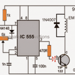
Circuit Diagram
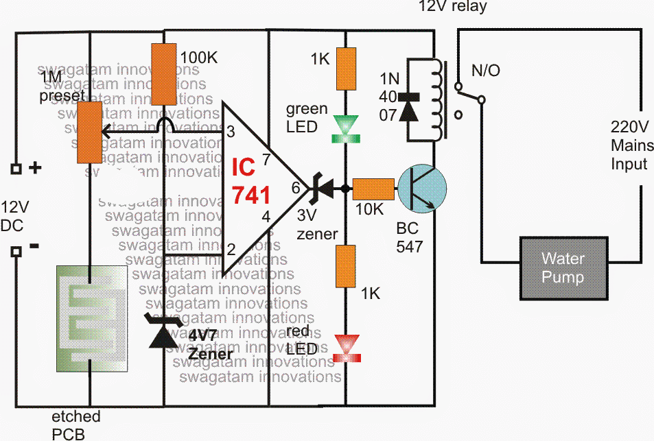
Referring to the above simple water sensor circuit we can see how the automatic evaporative air cooler operation is implemented with the help of a simple opamp comparator circuit.
How it Works
The opamp 741 is used here for comparing the voltage difference across its input pinouts pin#2 and pin#3.
pin#2 is referenced to fixed 4.7V via a zener clamp, while pin#3 is terminated to a copper etched PCB to ground through a 1M preset.
The etched copper PCB is attached firmly with the evaporative pad such that the water content in the pad comes in direct contact with the etched copper layout of the PCB.
The water content across the PCB allows current to pass through to the ground, and in turn causes the potential level of pin#3 to go below the reference level of pin#2, this can be of course determined by setting the 1M preset appropriately, so that the detection is achieved at the correct wetness level.
Therefore as long as the moisture level on the PCB is detected to be within the optimal range, pin#3 potential continues to be lower than the pin#2 reference potential, which cause a low logic to be held at the output pin#6 of the IC.
This is indicated by the illumination of the green LED, and this also keeps the transistor and the relay in the switched OFF position.
However, the moment a low moisture content is sensed over the PCB layout, pin#3 potential tends to go above the pin#2 potential consequently causing the output pin#6 to go high.
The transistor and the relay responds to this and the pump motor is activated enabling an automatic water filling and drenching of the evaporative pad until its wetness level is optimally restored, which prompts the opamp to switch OFF the relay and the pump until the next cycle.
How to Connect Pump Motor and Fan to an Evaporative Cooler System
The following diagram shows how to connect a water pump and a fan to an evaporative cooler system, to enable an automatic cooling operation.
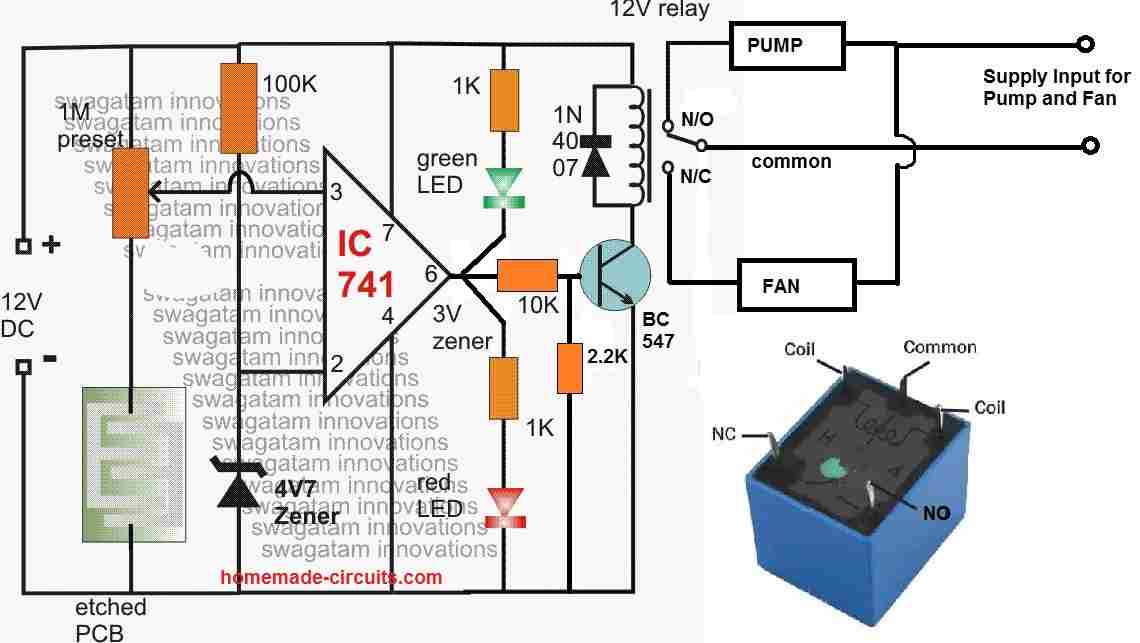
When the evaporative pad is dry, the etched PCB resistance is high which causes pin#3 potential of the IC to become higher than its pin#2 reference potential.
Due to this, the output of the IC becomes high, toggling ON the relay. The relay switches ON and its contacts move to N/O point which switches ON the pump motor. The pump motor begins spraying water on the evaporative pad.
After some time the evaporative pad's wetness increases to a point which causes the resistance of the etched PCB resistance to drop significantly.
Due to this, the pin#3 potential of the IC drops below its pin#2 potential causing its output to go low.
When this happens the transistor and the relay switch OFF, causing the relay contacts to move to its N/C point.
Since the fan is connected to the N/C point of the relay, the fan now switches ON causing cool air to be pulled out from the wet evaporative pad.
During this course of action, the evaporative pad slowly begins drying up, until it dries up to a point where the etched PCB resistance increaes significantly and the operation is reversed.
The above function keeps repeating ON/OFF automatically.
Questions & Answers
is it safe to proceed, how an evaporative pad can be placed in the etched pcb.
It is safe according to me. You just have to attach the etched PCB on the evaporation pad…
Thankyou for the response,where can I attach this circuit to a fan. As this automatic evaporative air cooler works on the condition of evaporation on evaporative pad and the water pump activates.
In the diagram you can see that the N/O contact is connected to the water pump, so the N/C contact can be wired with a fan. So when the water pump has soaked the evaporation pad, it is switched OFF and the fan is switched ON.
thankyou , we have to do again an timer based water level for the switching of water pump.
OK no problem, let me know if you have any questions.
How can I implement the switching on water pump can you explain me and how the fan gets cool air.
I have updated the required information at the end of the above article….you can check it out.
Your Update on the article was more useful and helpful, but what is the water pump circuit and how can I make it spray on the evaporative pads. your update tells how water pump works and not about how to connect a pump.
You can search for a “6V water pump” then you can connect this pump with the relay contacts as shown in the diagram. I can only help with the electrical and electronic connections, mechanical fittings will need to be figured out by the user.