In this post I have explained how to build a homemade LED driver with dimmer and charger circuit for illuminating a 3D moon from a 5V USB source.
The idea was requested by Mr. John Sweden.

Circuit Objectives and Requirements
- I've been a visitor to your website for many years and wonder if I may ask your advice please.
- My friend in the US has an almost 2-year-old grandson who loves the moon! I hope it shines in his life as it has in mine. I'm a little older than he is (75) and have recently started to explore 3D printing on an Ultimaker 2+ printer.
- I would like to print him a 3D moon-sphere bedside lamp, maybe 12 to 15cm in diameter. It will be hollow and will use a model created by NASA with a hi-res representation of the moon with its craters and surface features.
- The white PLA (polylactic acid) filament I'll use is translucent and will allow a small LED to light it from the inside.
- The light I was hoping to use is a small-footprint, rechargable battery-powered PCB module made in Malaysia but no longer manufactured. The module slides in through a hole in the bottom of the moon and the whole thing sits on a base.
- The Malaysian module is described as:
Micromake 3D Moon light touch circuit board 200 mAh yellow dual color touch infinite dimming. - An example from AliExpress descibes it as: 240mAh Lipo rechargable battery, 0.5 watts, USB DC 5v, charging time 6 - 8hrs, stepless adjust touch switch and on/off.
- Do you know of a DIY circuit or module in your library that might be suitable for this project?
- I very much appreciate your help Swagatam!
Designing the DC LED Driver
As per the request, for illuminating the 3D moon with a natural feel, we would require a bi-color power LED, 5V LED driver circuit, a current controlled Li-Ion Charger, a touch operated switch and a Li-ion Cell.
I have selected higher specs for all the parameters for the present design, however for lower specs, the materials can be scaled down appropriately as per user preference.
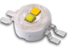
LED Specs:
Battery Specs:
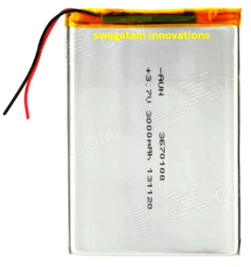
The battery can be a standard Li-ion or Lipo Cell rated at 3.7V, 3000mAh.
The Circuit schematic:
Circuit Operation
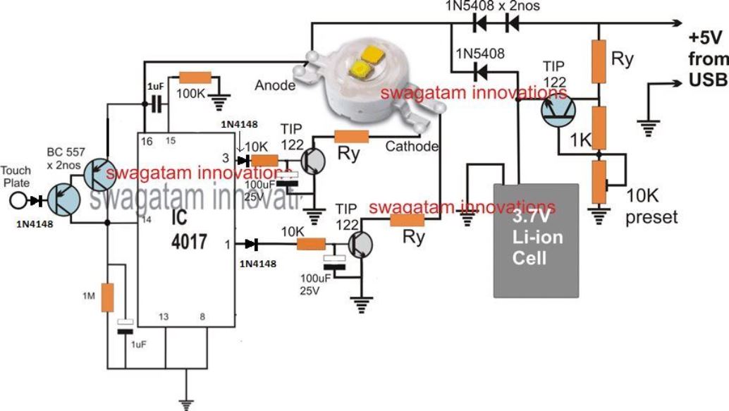
Referring to the above shown touch operated 3 D moon LED driver with charger dimer circuit, the supply input is obtained from a 5V source such as a USB, which can be assumed to be a constant voltage input.
The TIP122 along with Ry and the associated resistor, preset forms a simple current controlled charger circuit for the attached Li-Ion. The preset is adjusted to fix an approximately 4V across the Li-ion cell terminals.
Ry is appropriately calculated to make sure that the current to the battery never exceeds the 0.5C rate, which may be around 1.5 amps for the proposed 3000mAH battery. This TIP122 must be mounted over a suitable heatsink.
Ry may be calculated a follows:
R = V/I = (5 - 4) / 1.5 = 1/1.5 = 0.66 ohms,
wattage = 1 x 1.5 = 1.5 watts, or 2 watts
The DC to DC UPS Stage:
In the adjoining stage, we can see a few 1N5408 diodes positioned for creating a DC to DC UPS feature, which ensures that the LED inside the 3D moon continues to remain illuminated without an interruption even while the 5V USB source is removed or during a power failure, with the help of an automatic back up from the Li-ion cell.
The Touch Operated LED Dimmer Stage:
The next stage which is built around the IC 4017 forms a simple LED dimmer circuit. The pinout functioning of the IC 4017 can be learned with the following points:
Pin#3 which is the start pin of the IC and is supposed to be activated during power switch ON, is connected with one of the LED cathode pins through a TIP122 driver stage and a current limiter resistor Ry.
Let's assume this LED pin to be associated with the warm yellow color section of the LED, and will be responsible for generating a warm yellowish effect on the 3D moon illumination.
The next subsequent pins of the IC 4017, namely pin#2,4,7,10 are all supposed to incorporate identical TIP122 stages with varying Ry values connected and associated with the warm yellow pin of the LED.
The pinout details are not shown in the diagram due to lack of space, and since it is identical to the TIP122 stage attached with pin#3 of the IC and just needs to be replicated. The only difference being the value of the Ry which needs to be incremented suitably through calculation.
This implies that when these pins are sequentially toggled will enable a sequential dimming on the 3D moon LED brightness for the warm yellow section off the LED.
In exactly similar fashion pin#1 which initiates next to pin#10 can be seen associated with the other cathode pin of the LED through an identical TIP122 driver stage and a Ry current limiting resistor. The "cool blue LED" is supposed to get illuminated at this pin when the sequential toggling activates this pinout of the IC.
The following subsequent pinouts of the IC are supposed to have identical TIP122 stages for the cool blue LED side, as done in our above explanation with incrementing Ry values, connected with the cool blue pin of the LED.
When sequentially toggled pin#1 will illuminate the 3D moon with a cool blue bright light effect, and the next subsequent pins can be sequentially toggled for dimming this cool blue illumination to the desired lower levels.
As soon as the sequence reaches the last pinout of the IC 4017, which is pin#10, the sequence is designed to flip back to pin#3 and illuminate the warm yellow LED. In this way the 3D moon can be illuminated in two color with a sequential dimming effect.
The LED dimmer Switch.
The two BC557 attached to pin#14 of the IC 4017 are used for creating logic signals for the IC 4017 through finger touches, at the base of the BJT pair. Each touch results in a single sequential shift across the pinouts of the IC from pin#3 to pin#10 and back to pin#3 for the repetition.
Calculating the Dimming Resistor Ry
The Ry current limiter resistor and the dimmer resistor for the yellow and the blue sections of the LEDs may be calculated with the help of the following formula:
Ry = 4 - 3.3 / LED current
Here 4 is the input supply to the LED, 3.3 is the LED standard operating voltage, and the LED current is the amps which is responsible for implementing the dimming effect on the relevant sections of the bi-color LED. Therefore this current value needs to be calculated appropriately for enabling a sequentially decreasing current across the driver stages associated with the relevant pinouts of the IC 4017. Lower current selection will result in higher values resistors generating higher dimming effect on the 3 D moon illumination.
This concludes the making of the proposed 3D moon LED driver circuit with sequential dimming effect, if you have any doubts you may feel free to express them through comments...
Transistor Stage Configuration
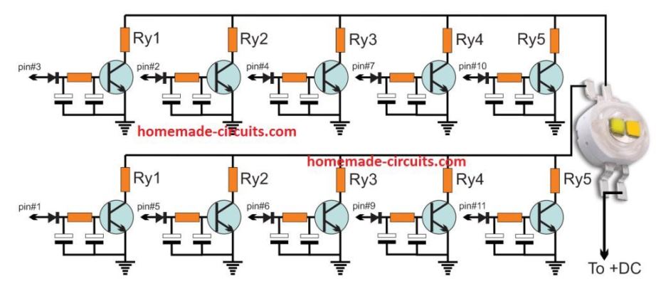
The following diagram shows how the TIP122 stage needs to be repeated for all the 10 outputs of the IC 4017:


Questions & Answers
Thank you Swagatam! Beautiful job!
Whenever you have time, could you please tell me where you sourced the LED? I’ve looked on Ebay and Aliexpress and have not found any with that package type.
Thank you,
Best wishes ~ John
You are most welcome John! here’s the LED link you are looking for”
….
I would be deleting this link after some time for obvious reasons 🙂
Sir which touch plate you used? is it any kind of sensor?
Amol, the touch plate is nothing but any metal contact.
4 Best Touch Sensor Switch Circuits Explored
Got it, thank you 🙂
Hello sir need a help regarding fm signal booster or receiver please provide circuit diagram
Hi Raghvendra, I am sorry, at the moment I do not have any circuit related to FM signal booster, if possible I’ll try to find one and post it for you…
Ok sir thanks
Sir there is a question that to ask you about the audio driver transformer which are used in professional amplifiers are the same or different from normal transformers which are used for step up and step down please do help full need
Thanks
Raghvendra, all trafos work with the same principle, therefore the audio trafo that you are referring to is also similar to the normal ones which are used in power supplies, except the winding ratio and the wire thickness.
Thanks sir for clearing my difficulty
Hello sir good morning
Sir recently i have brought an fm bluetooth module and connected to the 200 watt amplifier the circuit which was provided by you but the problem is that when i play it gives a countineous beep noise or sound please provide me the solution
Hi Raghavendra,
Is the amp working normally with other music sources?
Yes sir the amplifier is working good with other source but when it is connected with a particular module it is giving beep noise or sound
then it can be difficult to judge the issue, because it could be arising from the Bluetooth source, and its origin will need to be diagnosed then need to be blocked by some method.
Thanks sir
Hello sir good evening
Sir wanted to know about zobel network and why it is used in audio amplifiers and also if you have a data regarding audio driver transform winding please provide
Good morning Raghavendra, zobel network is already explained elaborately in many online sites you can get the required info from those sites….
sorry presently I don’t have the necessary details regarding how to calculate driver trafos.
Sorry sir its transformer winding
Thanks sir for your reply
I tried this, the touch switch is very noisy keeping the led shaking
increase the pin#14 1uF to 10uF and check again.
Hello good morning sir
Sir I need a help regarding step up boost converter to convert 3 or 5volt to 12volt will you please provide the details about the circuit
Thank you sir
Raghavendra
Hello Raghvendra, you can try the first circuit from this article, wire gauge will be according to the current specification. To reduce the voltage you can adjust the number of turns on the right side of the coil accordingly.
https://www.homemade-circuits.com/how-to-make-simple-boost-converter-circuits/
Hi sir,
Pls tell us detail ry rsister
All grounds or 0v pls
Hi Satheesh, the Ry calculations is already given in the article.
Ground itself means 0V in DC circuits
Thanks for replying sir,
Ry means pls
I am beginner pls help
Ry is a resistor. It controls current through the LED and safeguards it from burning due to over current.
I am using 300mah battery so any changes in circuit
For 300 mAh battery your LEd must be 50 mA rated. So instead of using a single biclor LEd use two separate 50 mA yellow warm, and blue cool LEds.
Thank u for reply sir
i want to add tri colour led to moon light instead of the dual led, how can i do it?
Then you will divide the 10 outputs of the IC 4017 into 3 sets, each with 3nos of TIP122 stage and Ry resistor, associated with the 3 LEDs respectively
i tried your circuit but did not connect battery as i want to direct power moonlight to work, can you please help. and also i am giving 3.3v to 5mm 2v led so which Ry i should use?
As shown in the diagram, the circuit is designed to work with 5V DC from an adapter and from the battery both. So connecting 5V DC from a power supply will allow the circuit to work perfectly without any issues. You can also use 12 V DC, but make sure to calculate Ry appropriately as per the supply input.
Ry can be calculated using the formula given in the explanation below the diagram
led stays continuous on and i am getting high current at pin3 of ic. when i touch the base of bc557 and led stays continuous on state then getting lower in voltage. can you help me out?
On each touch at the base of BC557, the voltage should jump from pin3 to pin2, then to pin4, pin7 and so on. To check if your 4017 is OK or not, you can manually touch the pin14 of the IC with the positive line….or replace the BC557 collector/emitter with a push button, for checking the same.
now its glowing but how to use dimmer in your circuit?
I think you should read the article fully, to understand the working correctly….you must repeat the transistor and Ry stage on all the 10 pins of the IC. for the first 5 stages, join all the Ry outputs and connect to the one LED input, and for the next 5 stages join all the Ry ends and connect with the other LED input. These Ry resistors must be calculated in an incremental manner so that the current is reduced to the LED when the 4017 outputs shift from one pin to the other in response to the touching of the BC557 base. The different resistor values of Ry will cause the dimming or brightening effect on the LEDs
does it stays on continuosly after touch? if possible can i talk on your mail id?
how do its diming function works?
Excellent circuit. I ask if it has the focusing mode to control three LEDs? I also ask you if you have your pcb? Thank you for your answer .
Thank you, glad you liked. By focusing mode, do you mean intensity control?
Sorry, I have not designed the PCB for this project yet.