In this post I will show how to construct a digital water flow meter using Arduino and 16 x 2 LCD display. We will be taking a look at YF-S201 water flow sensor, its construction and working and how to interface with Arduino to extract some useful readings.
The proposed project can measure the rate of water flow in litre / minute and total water flow in litres.
Let’s take a look at YF-S201 water flow sensor.
Illustration of YF-S201:
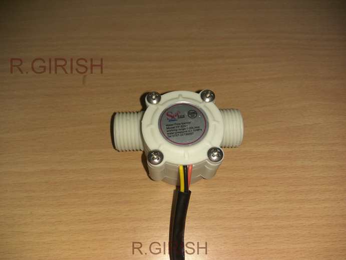
YF-S201 is a Hall Effect based water sensor. It has three terminals 5V (nominal working voltage), GND and output. The +5V is red coloured wire, the black one is GND and yellow one is output.
The sensor gives out frequency directly proportional to water flow. The YF-S201 sensor can measure from 1 litre / minute to 30 litre / minute. The water pressure should be less than or equal to 1.75 MPa.
The water can be injected from one end and water flows through the other end.
The sensor may be placed after the main gate-valve of tank; if you want to measure the water flow in a network of water pipes or you can place just before a water tap to measure the water flow of single tap.
The placement of the sensor can be anywhere according to user’s need but, care must be taken to avoid leakage of water.
The sensor has a magnet and Hall Effect sensor; if we take a look at the sides of the water flow sensor, we can witness a plastic turbine in the path of water flow.
A round shaped magnet is embedded at the center of the turbine and the Hall Effect sensor is sealed and protected from moisture and placed above the magnet. The Hall Effect sensor produces a pulse for every revolution of the turbine.
Water Flow Waveform on Serial Plotter
We can see the pulses generated by water flow sensor on serial plotter of arduino IDE, shown below (Using Arduino Single channel Oscilloscope).
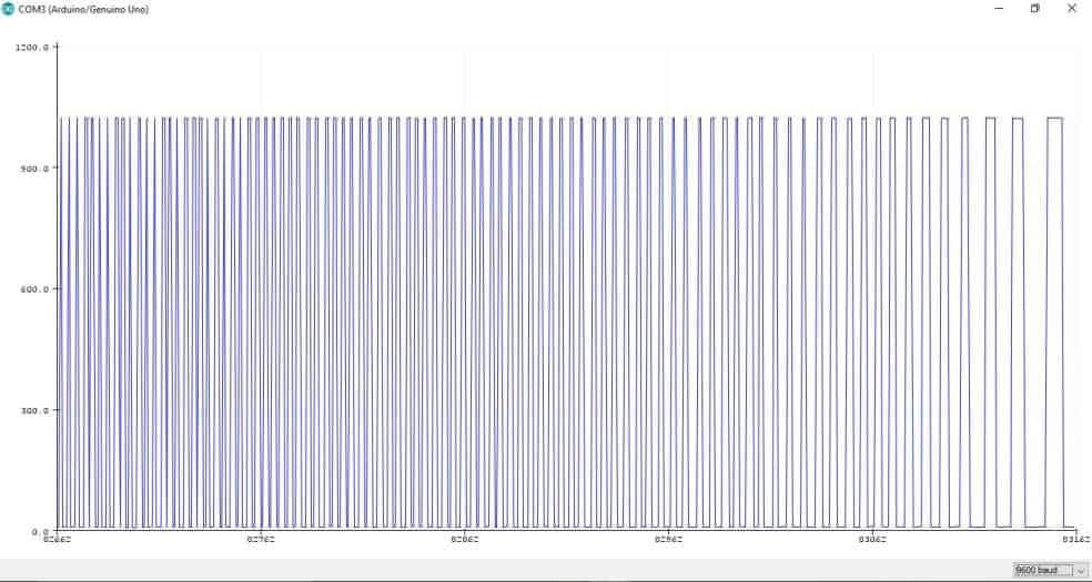
We have blown air through the sensor to rotate the turbine as a test and the waveform generated is shown above. The denser waveform on left hand side represents higher frequency and faster rotation of turbine, the less dense waveform at right hand side signifies the vice versa.
A consistent water flow gives out consistent frequency output.
We have to convert the frequency into litre/minute scale. To do this, the manufacturer has given a formula:
Water flow rate (litre/min) = frequency / 7.5
So, we need to measure the generated frequency and apply the above formula in the program code.
Technical Specifications of YF-S201:
· Accuracy: +/- 10%, if you need better precision, we need to calibrate.
· Working Temperature: -25 to + 80 degree Celsius.
· Working humidity: 35% to 80% RH.
· Output duty cycle: 50% +/- 10%.
· Maximum water pressure: 1.75 MPa.
· Pulses per Litre: 450.
· Maximum current draw: 15 mA at 5V
That concludes the YF-S201 water flow sensor.
Now let’s move to the schematic.
Schematic Diagram:
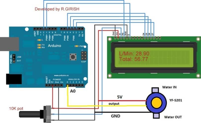
The water flow sensor’s output pin is connected to A0 of Arduino. Use the 10K potentiometer for adjusting display contrast. Wire the Arduino and LCD display as per the above diagram.
Program Code:
//-----Improved Version, Based On Original Design-----//

#include <LiquidCrystal.h>

LiquidCrystal lcd(12, 11, 5, 4, 3, 2);

unsigned long X, Y;
float Time = 0;
float frequency = 0;
float waterFlow = 0;
float total = 0;
float LS = 0;

const int inputPin = A0;

void setup() {
  Serial.begin(9600);
  lcd.begin(16, 2);

  lcd.setCursor(0, 0);
  lcd.print("Water Flow Meter");
  lcd.setCursor(0, 1);
  lcd.print("Initializing...");
  delay(2000);

  pinMode(inputPin, INPUT);
}

void loop() {

  // Measure pulse widths
  X = pulseIn(inputPin, HIGH, 1000000);
  Y = pulseIn(inputPin, LOW, 1000000);

  if (X == 0 || Y == 0) {
    // No pulses detected
    lcd.setCursor(0,0);
    lcd.print("L/Min: 0.00     ");

    lcd.setCursor(0,1);
    lcd.print("Total: ");
    lcd.print(total);
    lcd.print(" L   ");

    delay(500);
    return;
  }

  Time = X + Y; // microseconds
  frequency = 1000000.0 / Time;
  waterFlow = frequency / 7.5;
  LS = waterFlow / 60.0;
  total += LS; // accumulate liters

  // LCD update without flicker
  lcd.setCursor(0,0);
  lcd.print("L/Min: ");
  lcd.print(waterFlow, 2);
  lcd.print("   ");

  lcd.setCursor(0,1);
  lcd.print("Total: ");
  lcd.print(total, 2);
  lcd.print(" L   ");

  Serial.println(waterFlow);
  delay(500);
}
Author’s Prototype:
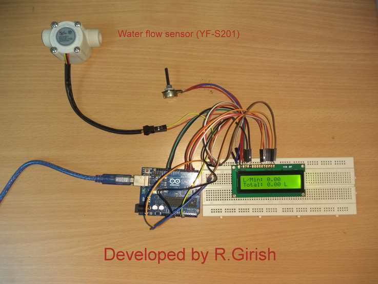
The “L/Min” indicates the current water flow rate and the “Total” indicates the total water flowed since the circuit turned ON.
You can also flow any liquids whose viscosity value is near to water.
If you have any questions regarding this digital water flow meter using Arduino, feel free to express in the comment section, you may receive a quick reply.


Questions & Answers
Water pressure should be less than 1.75 mpa so . sir can we use this project for petrol pump pressure. Because im not sure about the pressure of petrol pumps in mpa thankyou
Hi Shaihk,
Petrol should work fine with this sensor. I won’t recommend using with petrol or any expensive liquids because this sensor has tolerance of +/- 10%. Meaning you will end up in pumping 10% more or 10% less petrol.
Regards
can you give the flow chart of this program?
Hi
is it possible to add an Eprom Memory to the circuit in order to keep the consumption over time even the power is turned off? I suppose some changes must be done also over the code. Can You solve this issue ? Thank You!
Hi Wexler,
Yes, we can add an SD card or utilize built-in EEPROM of ATmega 328P for saving data. We can provide you the solution.
Customized Arduino code is premium as of now , if you are interested comment with your detailed requirements, we will proceed.
Regards
sir, i know that connecting LCD to potentiometer is for adjusting brightness but why did you connect the 5v pin of the flow sensor to the potentiometer? can i know why is that connection needed?
HI Rahul,
Look at the circuit carefully, the 5V line is common for the potentiometer and flow sensor, it is just 5V path, red wire.
Regards
Sir kindly answer my question
I made a transformer which have primery winding is 220 turn(18 swg wire 1kg) and secondary turn is 22 turn(10 swg 650gram) now the input voltage is 210 volt and output is 18 volt
bobin size is ( 6inch×3inch) how much current given in output ?????
Plz answer my question
Afrid,
It cannot be possible to judge the current through a visual analysis…you will have to check it with an ammeter.