In this interesting post, we are going to make a simple single channel oscilloscope using Arduino and a personal computer, where the waveforms will be showcased on the PC’s display and frequency and time period of the input waves will be displayed on the 16 x 2 display.
Introduction
Every electronics enthusiast once said “I have a dream, one day I will purchase an oscilloscope” but, it is still dream of many to own a decent oscilloscope for their projects and experiments.
The oscilloscope being expensive equipment even for an entry level model, we consider them as a luxury electronics tool and we might bring our experiments and projects to halt because we can’t afford one.
This project might be a game changer for many, electronics enthusiasts no need to spend tons of money for an oscilloscope to measure basic parameters of a wave.
The proposed idea has very limited functionality so don’t expect the features on a high end oscilloscope to be present in this project. We get three solid functionalities from this project:
1) visual representation of waveform on computer’s screen
2) frequency measurement of the input wave
3) Time period measurement of input wave in microseconds.
The frequency and time period of the signal will be showcased on 16 x 2 LCD display. There are two methods for visually representing the waveform on the computer screen which will be described in later part of the article.
Now let’s dive into technical part of the setup.
The proposed setup consists of arduino which is the brain our project as usual, a 16 x 2 LCD display, IC 7404, 10K potentiometer and a computer preferably a windows machine.
The arduino is brain of the setup and we must choose Arduino UNO or Arduino mega or Arduino nano for this project since other models doesn’t have built-in USB to serial converter which is essential for communicating between Arduino and computer.
If we choose other models of arduino board we need external USB to serial converter which might complicate the project.
Illustration of LCD to Arduino connection:
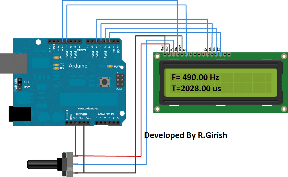
The above circuit is self-explanatory. We can find similar connection between the display and arduino on other LCD based projects.
The 10K potentiometer is used to adjust the contrast of the 16 x 2 LCD display which must be set by the user for optimum view.

The function of IC 7404 is to eliminate any noise signal from the input and fed to frequency sampling pin A0. The IC 7404 only outputs rectangular waves which is a great advantage for arduino, since arduino is more capable of processing digital signal than analogue signals.
Program:
//-----Program Developed by R.Girish (Optimized & Pin-Matched)-----//
#include <LiquidCrystal.h>

// LCD connections as per Image 1
// RS=12, E=11, D4=5, D5=4, D6=3, D7=2
LiquidCrystal lcd(12, 11, 5, 4, 3, 2);

unsigned long X;     // pulseIn returns unsigned long
unsigned long Y;     // pulseIn returns unsigned long
float Time;
float frequency;

// Pin definitions mapped exactly to your 7404 Hardware Diagram (Image 2)
const int Freqinput = A0;  // Connected to Pin 2 of IC 7404
const int oscInput = A1;   // Connected to raw Freq INPUT line
const int Switch = A2;     // Connected to the Push Button with 10K pull-down
const int test = 9;        // Left unconnected or used for independent testing

void setup()
{
  Serial.begin(9600);
  lcd.begin(16, 2);

  pinMode(Switch, INPUT);
  pinMode(Freqinput, INPUT);
  pinMode(oscInput, INPUT);
  pinMode(test, OUTPUT);

  // Generates a ~490Hz test PWM signal on pin 9 if you ever want to test
  analogWrite(test, 127);

  lcd.setCursor(0, 0);
  lcd.print("Press button for");
  lcd.setCursor(0, 1);
  lcd.print("Freq Counter...");
}

void loop()
{
  // Check if the push button is pressed
  if (digitalRead(Switch) == HIGH)
  {
    // Read pulse widths in microseconds (with a 1-second timeout)
    X = pulseIn(Freqinput, HIGH, 1000000);
    Y = pulseIn(Freqinput, LOW, 1000000);

    Time = X + Y;

    lcd.clear();

    // Check if Time is 0 to completely prevent a division-by-zero crash
    if (Time == 0)
    {
      lcd.setCursor(0, 0);
      lcd.print("F= 0.00 Hz");
      lcd.setCursor(0, 1);
      lcd.print("T= 0.00 us");
    }
    else
    {
      frequency = 1000000.0 / Time; // 1,000,000 microseconds = 1 second

      lcd.setCursor(0, 0);
      lcd.print("F= ");
      lcd.print(frequency);
      lcd.print(" Hz");

      lcd.setCursor(0, 1);
      lcd.print("T= ");
      lcd.print(Time);
      lcd.print(" us");
    }
    delay(500); // Hold the data on screen for half a second before next read
  }
  else
  {
    // When button is not pressed, stream the raw input signal to the Serial Monitor/Plotter
    Serial.println(analogRead(oscInput));

    // Update the screen to prompt the user
    lcd.setCursor(0, 0);
    lcd.print("Streaming Osc... ");
    lcd.setCursor(0, 1);
    lcd.print("Hold BTN for Freq");

    delay(50); // Small delay to avoid flooding the Serial buffer
  }
}
//-----Program Developed by R.Girish-----//
Once you completed the hardware part and uploaded the above code. It’s time to plot waveform on the computer screen. This can done in two ways, the easiest and laziest way is described below.
Method 1:
• Connect the input wire to pin #9 of arduino (Test mode).
• Open the Arduino IDE (it must be 1.6.6 or above versions)
• Go to “tools” tab and select serial plotter
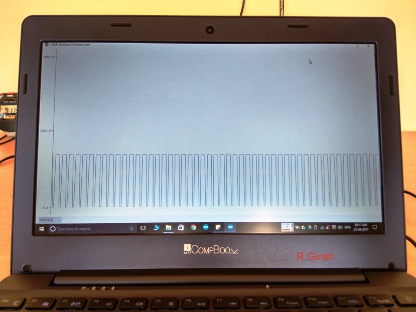
As soon as the serial plotter opens you can see the rectangular wave which is generated from arduino’s pin #9, illustrated below.
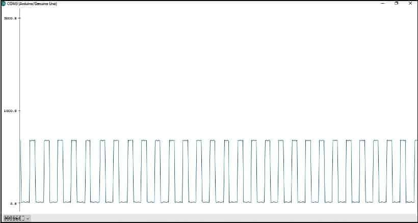
Press the push button to show the readings and also for refreshing the readings the LCD display, it must show around 490Hz on “test mode”.
Schematic of test mode:
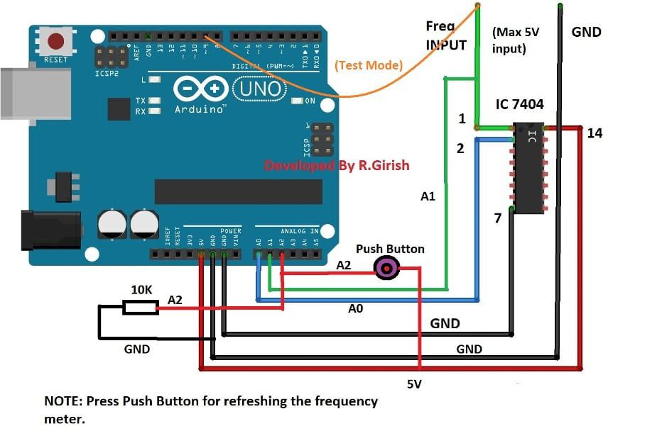
The test mode is to check proper functioning of the oscilloscope. The pin #9 is programed to give 490Hz output.
Method 2:
This method is relatively easy but we need to download software from the given link:
http://www.x-io.co.uk/downloads/Serial-Oscilloscope-v1.5.zip
This software will give us little more control and features compare to arduino’s serial plotter. We can zoom in and out of the generated waveform; we can set trigger functionality, offset control over vertical and horizontal axis etc.
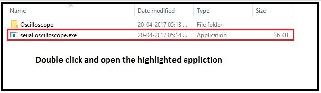
• Download the software and extract.
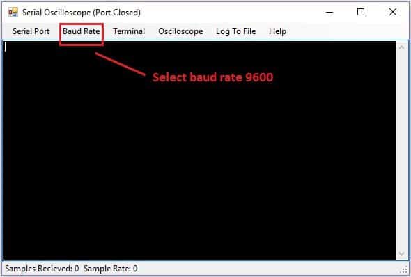
• Now double click on the Serial Oscilloscope application.
• A window will pop-up as illustrated below and select baud rate to 9600.
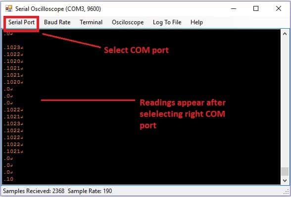
• Now select “Serial port” tab and select the right COM port which can vary computer to computer. If you select the correct COM port, you can see readings as illustrated below.
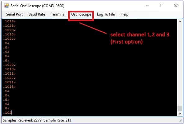
• Now select “oscilloscope” tab and select “channels 1, 2 and 3” (first option).
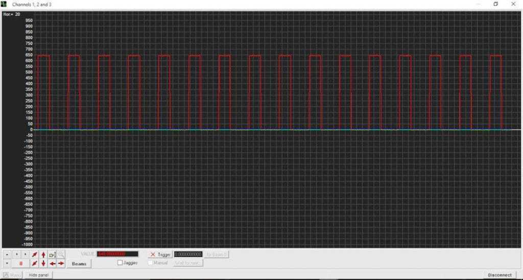
• You can see the generated test signal from Arduino as illustrated below.
As you can see there are some control buttons on the software by which you can analyze the waveform better.
NOTE:
The proposed setup has one major disadvantage:
The Arduino cannot show input waveform on computer screen and frequency/time period reading on LCD display simultaneously. To overcome this issue a push button is provided for reading/refresh the frequency and time period on the LCD display.
Once you press the button it will show the frequency and time period on LCD display at the same time waveform will freeze on the computer screen as long as you keep pressing the push button.
You may also consider this as an advantage since you can stop the frequency on the computer monitor at any instant and this may give you time to analyze displayed waveform.
Author’s prototype:
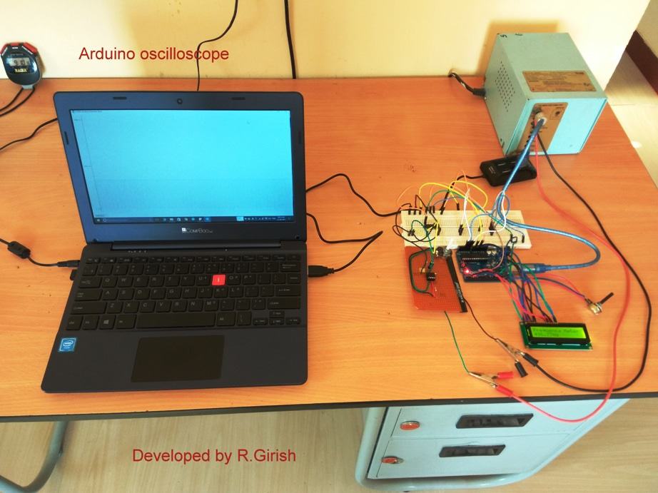
If you have any further queries regarding this simple single channel Arduino oscilloscope circuit, please feel free to use the below comment box for expressing your specific views


Questions & Answers
What is the max frequency that it can handle?
Hi Swag,
Great news. I have successfully built this project. it is working great. sharing images with you. thanks for great blog.
https://ibb.co/dbBofb
https://ibb.co/nAFELb
https://ibb.co/ekwofb
https://ibb.co/cPvg0b
Thanks a lot Saqib, congrats on that.
I am sure the other folks here will also love those pics and your success.
Hi Swag,
While compiling the above Arduino code I am getting errors. I not good in hardware microcontroller programming. can you please check and fix the code. the errors are below;
Oscilloscope:4: error: stray ‘\302’ in program
int X;Â Â Â Â Â Â Â Â Â Â Â Â Â
^
Oscilloscope:4: error: stray ‘\240’ in program
Oscilloscope:4: error: stray ‘\302’ in program
Oscilloscope:4: error: stray ‘\240’ in program
Hi Saqib,
it is copy/paste errors.
Copy the code from this site and paste directly to Arduino IDE.
If it didn’t work, go to (Arduino IDE) “Tools” > Auto format.
I just copied and pasted on the IDE directly and found no errors and code complied successfully.
I think you are using some code editing tool or something like that and copied from there.
If any errors arise further, notify us, we will help you out.
Regards
Swag,
This was from your blog. my Microsoft Edge copied invalid chars. shared my completed project images in previous comment. thanks GR and Swag for great tool. it will really help us.
OK got it, thanks, appreciate it!!
Thanks GR, The problem is solved now, but not sure whether Mr. Saqib was referring to your above article or some other external article….
Hi Swag, No need now. I have fixed the problem. the problem was copying and pasting the code from website to Arduino IDE.
It’s perhaps because I copied code from website which has perhaps not an ASCII encoded page, but UTF-8 encoded page. So to solve this issue I just copied all code in visual studio C# file and then replaced qomma and semicolons and the copied that code to Arduino IDE and it worked.
Btw thanks for your prompt response.
One more thing, I have successfully built frequency meter using Arduino which was in your blog and it worked perfectly. now I am making this oscilloscope because it has frequency meter and wave visuals. I am almost done with it. hopefully it will work.
Hi Saqib, I thought you were referring to the above article, so was it from some other website??
Hi Saqib, I’ll forward this message to Mr.GR, he’ll reply you soon…
Sir, I can’t find schematic of 7404 (that I saw it in old version) in this new version
Sir, can I use 74HC14 to replace 7404 ? Thx, for all – sir
yes 74HC14 will also work, just make sure you replace the pinouts correctly…
Sir, I built it – but my lcd16x2 didn’t work & I got 1020 amplitude on my laptop screen, any suggestion to solve ? Thx U, sir
Hi Jappar,
You have to press the push button, only then LCD screen shows the Frequency and Time period.
Can you say which signal source did you use as input, the built in test signal 490 HZ? or external signals?
To visually the see wave form which one you did you use: serial plotter or serial oscilloscope software?
Please give me a insight reading the above.
* Please give me a insight regarding the above.
Jappar, I’ll forward this to Mr.GR, he will reply soon
Pls can you give a circuit diagram for video mixer with this features. Av & VGA inputs and Av & VGA outputs.
Hi,
It is not possible to add VGA output/input from arduino.
Regards
I have posted the required circuit here
https://www.homemade-circuits.com/2017/04/lifi-internet-transmitter-circuit.html
you can discuss your queries under the same article if any…
Ndidi, It might take some time because the concept is a little confusing.
the USB data has positive negative push pull signals which the LED light won't be able to differentiate…to correct this we may have to modulate the two signals but modulation could cause distortion of the actual signal?
If it's possible I'll surely post it for you…
You can try the following circuit
https://www.homemade-circuits.com/2012/04/how-to-make-simple-programmable-timer.html