In this post I have explained a simple super capacitor hand cranked charger circuit using bridge rectifier which may be applied for charging a bank of super capacitors through any suitable hand cranked generator machine. The idea was requested by Mrs. Janet
Prevent Reverse Discharge in Super Capacitors
For a DIY project I bought a 24 V, 25 Farad Super capacitor Module sometimes ago here:
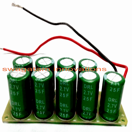
But I need to stop the reverse polarity that always occur whenever I'm charging it with an hand crank 24Vdc generator.
Please Swag, what exact Diode should I use? How do I get the positive and Negative terminals of the Diode in order to solder correctly the Diode to the Super-cap Module?
Thank you in advance.
P.S: please if possible, give me a pictorial guide.
Thank you a Million times.
Circuit Schematic
The Design
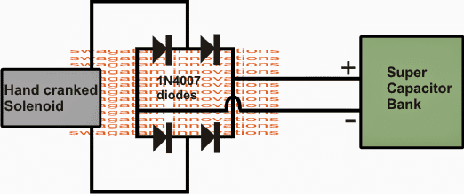
The solution to the proposed super capacitor hand cranked charger circuit is very simple, it's by using a bridge rectifier for the required DC conversion across both the cycles of the AC.
As we all know a bridge rectifier is configured in such a way that the connected diodes become equipped for rectifying an AC through both half cycles applied across it.
The preferred hand cranked alternator device also acts like an AC generator wherein the forward motion of the cranking produces a forward or a positive current while the retracting action in the device does the opposite and develops a negative current across its outputs.
Therefore if the wires of the hand cranked generator or any generator are connected directly with a filter capacitor which is a super capacitor in the present case would charge the capacitors during the first motion and immediately discharge the capacitor during the reverse motion of the cranking, resulting in a net zero charge inside the capacitors.
When a bridge rectifier is connected across such a generator as shown in the diagram, both the positive and the negative currents across its output are appropriately transformed into a single polarity voltage which helps to charge the super capacitors effectively without inflicting any loss across the capacitors.
How to Solder Bridge Rectifier with Super Capacitor
Thank you again for keeping up with your promise.
But please I am sorry, I do not fully comprehend the know-how on how to solder the diode in series as you Pictured it.
What exactly it is that I do not know is how to get the positive and Negative terminals of the Diode in order to solder correctly the Diode to the Super-cap Module?
Also, when I get the positive and negative terminals, will I solder the Positive leg of the Diode to the Positive terminal of the super cap and do the same to the Negative terminals?
Please forgive me for my silly questions.
P.S: In the datasheet I saw Max. Reverse Current:1A and Max. Forward Current:30A
What does this mean?
My Super Capacitor Maximum Output Current is 5A and Voltage is 24V. How many of the Diodes in the above link will I need to solder on to my Super cap?
Is it possible to Simultaneously charge super capacitor and Discharge it? Is such practice safe?
Thanks.
Solving the Circuit Queries
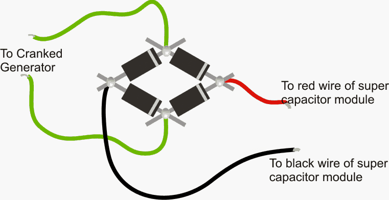
I have attached the diagram in pictorial form, please check it out
The reverse current will matter only in case if the red/black wires are reversed while connecting with the super capacitor.... the capacitors will get damaged if the current in this condition exceeds 1 amp.
The 30 amp suggests the max current tolerance in normal conditions as given in the attached image.
But still it will matter only if the voltage from the generator tends to exceed the max voltage rating of the super capacitor..
If it remains within the capacitors voltage range the forward current tolerance becomes immaterial and may be ignored....so please confirm the generator's maximum voltage, it must not be more than 24 V for the indicated super capacitor module.
The diodes in the bridge could be 1N5408 for ensuring complete safety to the system.
The super capacitor can be charged/discharged at will thousands of times irrespective of any precautions or care.


Questions & Answers
Hi, I am trying to make a hand crank flashlight with a stepper motor. I have a unipolar stepper motor that I have “converted into a bipolar stepper motor” by removing the trace between the centre tap. I have 4 bridge rectifiers set up (one for each of the leads from the stepper motor), as well as a 5.1V zenner diode to act as a voltage regulator across my capacitor. I wanted to use a larger capacitor (like 4F, 5.5V), but it wasn’t working. It only worked with a 0.1F 5.5 capacitor. Why is that? Also, it drains very quickly. How can I know which capacitor to choose for my circuit? Is there a way to calculate which capacitor would be best for my flashlight generator? Or any current generating circuit?
Thank you in advance!
Hi, Can you please specify the maximum voltage your motor is able to supply? I think the 5.1 V zener could be wasting some precious energy from the motor. The capacitors are not charging strongly probably due to a low current supply from the motor and also due to the energy loss caused by the zener.
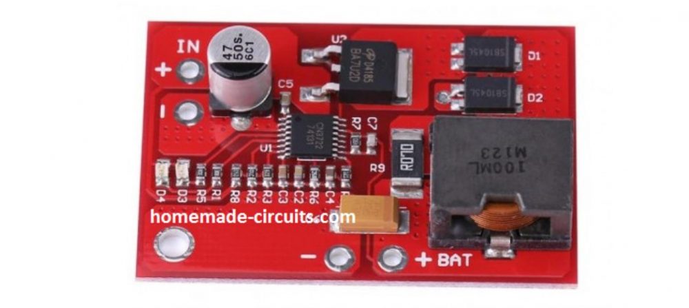
If your motor is able to generate higher levels voltages in the range of 9 to 12V in that case you could try employing a 12 V to 5 V buck converter, which would significantly enhance the charging power of the capacitors. However, the mentioned buck converter would be useful only if the motor is generating above 9 V.
You can buy these buck converter easily from any online store like amazon, ebay etc
The stepper motor is a small 5V motor (28BYJ-48, converted into bipolar), and the zenner is hooked up in reverse bias, parallel to the capacitor, to ensure only 5V travels through the capacitor. How can I know which capacitor to choose for my circuit? Is there a way to calculate which capacitor would be best for my flashlight generator? Or any current generating circuit?
If the motor is not generating over 5 V then the zener will not cause any power drain.
The Farad value determines the current storing and delivering capacity of the capacitor while the voltage rating indicates its maximum breakdown capacity to supply voltage.
However, if the motor is not able to produce sufficient amount of current then increasing the Farad rating will not help. In your case it seems the motor is too weak to charge the high value capacitors optimally.
i have built similar circuit with 1f 5v5 button capacitor to lit several led's. the capacitor drains quickly… can anything done to kep charge longer. (what is the drain time of 1f to lit 3v normal led?)
discharging rate will depend on the particular caps time constant…..
you'll have to increase the number of capacitors by connecting many such modules in parallel, the number of capacitors will be directly proportional to the backup time…the charger must be also correctly rated to ensure optimal charging of the caps.