In this post I have explained a 200 + 200 watt wireless home theater circuit using a class D amplifier and a Bluetooth headset as the wireless module. The idea was requested by Mr. Sudipta Mandal.
Technical Specifications
I want to make my home theater wireless. My home theater model is Sony SRS-D9 2.1 channel. I also want the audio to be stereo. Range should me minimum 2 meters.
Is it possible through Bluetooth module or RF transmitter & receiver?
If so please suggest how to connect these modules to transmit and receive audio signals. If it is possible through Bluetooth then how to connect the Bluetooth module to my home theater?
If a small circuit is required I can make it on my own but for that I need the circuit diagram and specifications of components required.
The Design
In one of the previous articles I have explained regarding the internal constituents of a Bluetooth headset gadget and in another post I have explained how its speaker pins could be used for activating a relay.
In response to the above request, in this article we investigate how a Bluetooth Headset could be used for making a home theater system circuit.
The idea is simple, it's about finding a suitable differential power amplifier circuit and integrating the Bluetooth Headset speaker wires with the inputs of the amplifier.
For the proposed application here we have used an example 200 + 200 watt class D power amplifier circuit using the IC TDA8953 from NXP Semiconductors.
The complete schematic of the power amplifier can be witnessed in the below given diagram. It includes two differential inputs meaning the chip supports a stereo class D input.
The output is single ended though and is capable of driving two ground referenced 4 ohm speakers rated at 200+ watts each.
Circuit Diagram
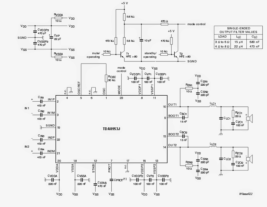
Image Courtesy: https://www.nxp.com/docs/en/data-sheet/TDA8953.pdf
Integrating with Bluetooth Headset
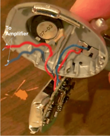
Each of the inputs of the above shown class D amplifier could be directly configured with the cut/stripped speaker wires of a scavenged Bluetooth headset circuit as given below:
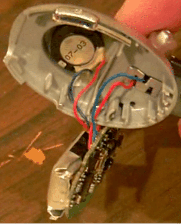
Disconnect the speaker wires from the speaker, strips the ends carefully for the recommended integrations with the amplifier inputs
For Stereophonic Response
For using both the inputs of the amplifier and for enjoying a stereophonic home theater response, another compatible and appropriately paired Bluetooth headset unit will be required.
Once the integration of the two Headsets, paired with source Bluetooth is done, a throbbing crystal clear class D 400 watt stereo music could be experienced over the attached speakers.
The system could be positioned as a home theater system or simply for enjoying a pure 400 watts of music from your cell phone or other Bluetooth compatible gadgets.
If you already have a ready made home theater amplifier system, connect the input of the amplifier with any one cut/stripped speaker wire of the Bluetooth headset (if the amplifier is not a differential type) and make sure the negative line of the headset is made common with the amplifier negative line.
Alternatively a bridge network could be employed for rectifying the differential output from the headset speaker and the output could be directly joined with the inputs of the single ended amplifier.
Comments
sir mera SRS D9 sony ka ici ud gya hai aur service center bhi nhi bna rha hai old model bol ke sir mko srs d9 home theater ka pura circuit chahiye mil jayega kya???
Manish, sorry I do not have the required information about your home theater system.
i have 6 channel tda 2050 boards———
bluetooth,fm,mp3 module———–https://sc01.alicdn.com/kf/HTB1rNxNKXXXXXX1XXXXq6xXFXXXf/225502313/HTB1rNxNKXXXXXX1XXXXq6xXFXXXf.jpg
dpdt switch——–6 legs–https://cdn.solarbotics.com/products/photos/b4692d34de8633c4fbd7939d674997cd/swt7-front-img_3280.JPG
———-i want to use bluetooth and 6 channel desktop pc audio out signal—–
———-do i require a switch to connect or not ?
—how do i connect bluetooth and pc signal together or by dpdt or without that—-so that i can switch signal sources whenever required ?
——thank you
sorry I have no idea about this problem.
ok
thanks for your reply, I will built it soon
if I ground input 2 of this stereo amp, will I get 400w mono amplifier?
not the input, rather if you connect the outputs in series with a single speaker, then you might get 400W
sir , i'm working on how to convert an old phone camera to cctv camera, besides i need a circuit and circuit diagram sir. In addition that old phone is no more working but the camera is still working.
Tun, I have no idea about it…you will have to find out how to configure the output from the camera circuit inside the phone with a Bluetooth device so that it is able to transmit the data to a nearby Bluetooth receiver
Hello Sir
Please tell how to Make Coil(LC1 and LC2) before speaker
Hello Sinu, it's an air cored inductor, the value is suggested in the diagram, or you can use any arbitrarily selected value such as by winding a 10 turn coil having a diameter of 10mm, since it's not too critical according to me..
HELLO Sir
I have to question
what is the voltage and current i should apply to this IC and what is the cost
how to make inductor(Lc1 and Lc2) of filter.
thanks and regards
you can use the following concept for rectifying the issue….just connect the speaker via the relay contacts, and power the circuit from the amp power supply
https://www.homemade-circuits.com/2013/02/make-this-simple-delay-on-circuit.html
Sir
One more thing as and when I switch On my music system There is loud Thud sound in woofer.
i think this will damage the woofer.
do you have any circuit for this
style, check datasheet of the IC for more info!
Hi Swagatham
I tried your suggesion.
1) 2diodes……bluetooth off, even status led not lit
2) 1diode……low battery warning message from speaker
3) 5v direct connection….bluetooth frequently disconnects itself.
4) 3.7v li-po or 4.2v li-ion battery…….bluetooth worked perfectly.
Then I tried an LM317T based 3.7v, 500mA supply…..bluetooth worked as I desired.
Thanks for your suggessions…..
Thanks,
With 2 diodes there will be a drop of around 1.2V, so the output will be 5 – 1.2 = 3.8V, with 1 diode this will be around 4.4V….so if the BT can work with 3.7V batt, then it should have worked with the above method too.
I think there's some problem with your 7805 or the diodes….
Hi Swagatham
I assembled a Bluetooth speaker system. For that, I used a broken, LG make Bluetooth headset's board. It is working perfectly.
Currently I run the BT section with the same battery ( 3.7V, 170mah Li-Po ). I want to remove battery and operate BT board using a 5VDC regulated supply using LM7805.
My doubt, can this BT board work with 5vdc, 1A supply tapped from the poweramplifier powersupply itself. Otherwise please suggest a suitable powersupply circuit. Thanks in advance.
Hi Anil, you can add 2nos 1N4007 in series with the output of the 7805, this will drop the 5V to 3.8V and will be safe for the BT
Hello Swagatam, can you please email me the cleat print of the amplifier circuit. I want to build the amplifier.
Hello Ajay, please check the diagram now, I have updated a bigger and a clearer one……