In the previous post I explained regarding the internal circuitry of a typical Bluetooth headset, in this post we'll see how a Bluetooth headset unit can be modified or "hacked" in order to make it work for other personalized applications.
In the previous article I have explained how to break open a Bluetooth headset device and also investigated the various components enclosed within.
Identifying the Speaker and MIC
Although most of the stages inside the headset appear to be too sophisticated to digest, the two elements which are still quite traditional are: the speaker and the mic, and those are exactly what we are interested in for implementing the proposed hacking procedures, because these two ports basically become the input and the output terminals of the device.
To be precise it's the speaker outputs that is more useful, which could be assumed to be generating analogue audio frequencies in a push-pull format. This analogue signal can be easily translated and converted into a logical signal for operating a toggling device such as a relay.
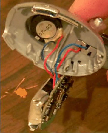
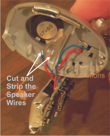
In the following couple of images we are able to see the speaker wires which could be simply cut and striped at the ends for accessing the processed analogue frequencies for the required modifications.
Integrating with a Bridge Rectifier Network
Once the above operations are made, it's all about integrating the wires with a bridge network followed by an opto coupler stage, as shown below:
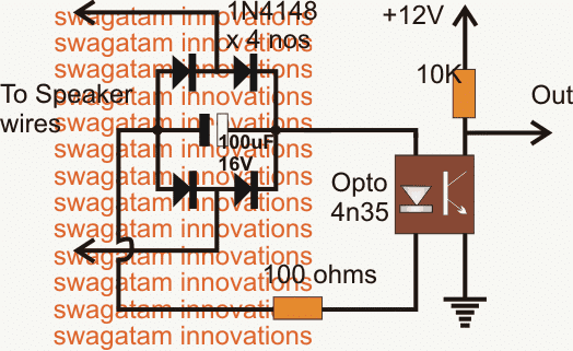
The bridge network converts the differential output response from the Bluetooth speaker outputs into a full wave DC, which is further filtered by the 100uF capacitor to produce a clean DC across the opto input.
The DC is converted into a logical content across the collector/ground of the opto transistor. This output may be configured with any standard flip flop circuit for toggling any desired load.
The above toggling could be initiated by activating the Bluetooth headset with a data from a cell phone or any similar compatible device. Each time the speaker responds, the info gets translated into the above discussed toggling effect over a connected relay.
The Flip Flop Bistable Circuit
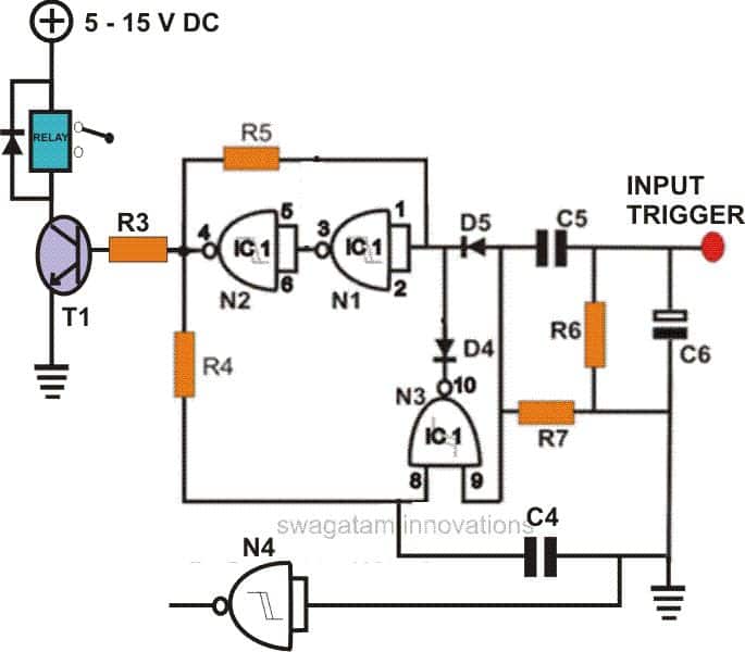
A flip flop circuit can be seen in the following figure which could be integrated with the above opto output for obtaining the intended relay operations.
Parts List
R3 = 10K,
R4, R5 = 2M2,
R6, R7 = 39K,
R4, R5 = 0.22, DISC,
C6 = 100µF/25V,
D4, D5 = 1N4148,
T1 = BC 547,
IC = 4093,
The above method explains an easy way of hacking a Bluetooth headset for remotely operating a particular appliance, in the next post (yet to be published) we'll learn how to hack a Bluetooth Headset as a wireless home theater system.



Questions & Answers
is there any other simple amplifying circuit that you can design for me to use with smaller size single speaker with my Bluetooth Earphone (ear pod), with detail connection step,without buying any Bluetooth receiver module . thanks
Ola, I am sorry, please ignore my previous comment, you airpods are itself working as Bluetooth receiver.
So you just have to follow the instructions as given in the above article.
Open your airpod, and inspect the connection of the earphone speaker with the internal circuit, now very carefully disconnect the ear piece from the circuit and replace the ear piece with the input of an amplifier.
You can use LM386 as the preamplifier here…
so connect the bluetooth wires (which was previously connected to the ear piece), with the LM386 input. Next, connect the LM386 output with any high power amplifier from this website. For the LM386 circuit, please refer to the following post:
https://www.homemade-circuits.com/ic-lm-386-datasheet-explained-in-simple/
Please help me out, I want to Convert my Single Speaker to Bluetooth wireless speaker, I have small Bluetooth Earphone that is working perfectly that I want to use for the conversion.The Speaker is rated as follows: Impedance 4 ohms, maximum power 260 Watt and the Second Speaker is rated: Impedance 6 ohms maximum power 50 watt.I want to convert anyone of the speakers base on your suggestion, please help me with simple circuit and detail steps to convert the speaker to Bluetooth speaker
Ola, for amplifying your Bluetooth signals into high watt speakers, you can simply procure a Bluetooth receiver module, then integrate it with the desired high power amplifier, and then connect the speaker with the amplifier output…
Can we install hidden all time real environment audio recorder with 64 gb hd card slot…in a bluetooth neckband headphones ????
great … mr. swagatam.
next post I hope you hack bluetooth for communications on a motorcyclist which inserted in each helmet
Thanks Ansar, I’ll try to update it soon. I assume it is for left/right turn signalling and brake lights?
Sir can you give me some flow code v5 examples
please sir can i use the Bluetooth hand set to replace the cod-less door bell light control system?
yes you can use it…
Excellent guide that gives me ideas. The optocoupler could be replaced by an optical fiber link, for controlled devices that are just out of BT range and/or out of sight. That fourth gate could instead look at pin 4 of N2 and operate a state-indicator LED visible at the BT end. See, I have an older Android tablet I want to use to control several remote locks, and it can handle five BT connections at once.
Do you know of any hacks that discard the BT functions, and just use the rest of the headset as a standalone rechargeable micropower supply for other projects not-BT-related?
the above circuit is designed by me….but I have no idea regarding the chips used in a BT module
OK understood, in that case you could probably try the second circuit from the following article:
https://www.homemade-circuits.com/2013/12/usb-automatic-li-ion-battery-charger.html
you could try SMD parts for making the unit truly compact.
What I meant was, to utilize just the battery and associated charging circuitry within your average BT headset to power small devices that don't need to communicate over BT.
I was asked by a friend who bought an expensive Green Lantern power ring "toy" when the (not very good) movie came out to find a way to replace the battery in it with something rechargeable. I noticed that there was room inside the ring for the LiPo battery in a BT headset I had opened up to see what was inside, and room to hide a USB charging port on the outside of the ring. Unfortunately the circuit board was a little too big to also fit, but I couldn't figure out which bits I could cut off without disabling the charging circuitry. I got lucky and found a tiny rechargeable that fit but it still required removal to recharge- I wanted to do it without disassembly and reassembly each time the battery needed charging.
Since then I've thought of several other ways that could be useful, but the chips in BT sets are hard to find data on- Google is spectacularly unhelpful. I was hoping that you might know of a website that collects that sort of information in one place.
Thanks very much!!
Sorry, but without the BT function the unit would have no other purpose, could you please explain how do you visualize the unit to serve the mentioned purpose with the BT discarded??
Hi Swagatam,please help me with a circuit design on how to connect ICL7107 with 2 digit 7 Segment display.Thanks
Thanks Vincent, however I am sorry to say this, I have no idea regarding how a 2-digit display may be configured with the mentioned A/D IC.
Thanks Swagatam am waiting and working for the next,
wow,,,,,,thanks so much swagatam………….just like others am really waiting and working for the next.
SIR I AM WAITING FOR YOUR NEXT POST. WHEN WILL IT COME. I AM EAGER TO BUILT IT
Arif, actually it's not difficult, you just have to buy a cheap home theater system and connect the speaker wires of the bluetooth headset with the headphone jack of the home theater….and it will start working like a bluetooth controlled home theater system….any music can be played wirelessly through bluetooth
WAITING FOR NEXT POST
thanks for reminding, I'll try to post it soon…
Wow ! GREAT AND GREAT PRODUCT
you are most welcome
Sir… great … waiting for next
thanks moonlite ! I'll post it out soon.