This is a RF jammer designed for the U.S. 800 MHz cellular phone band (870-895 MHz). This works by generating an overwhelming sweeping RF carrier on the cell phone handset's operating frequency range.
Circuit Operation
An Exar XR2206 Multi-purpose Generator is going to function as the triangle wave generator for supplying the sweep part of the jammer circuit.
The sweep generator is going to deal with a Z-Communications V580MC04 Voltage Controlled Oscillator (VCO) to sweep between roughly 850-895 MHz at a pace of around 100 kHz.
The VCO is certainly the key component in a mobile phone jamming process. It's a tad four-terminal gadget (Vcc, RF Output, Voltage Tune, and Ground) which translates into the preferred low-level RF output signal with a nominal degree of hassle.
Regrettably, VCOs designed to cover the intended frequency range we may need my not be easy to obtain. Manufacturers like Mini-Circuits and Z-Communications are particularly in favor of the amateur of electronics enthusiasts, who are ready to promote their VCO products in individually directly or provide you to a nearby supplier.
The VCO you decide on ought to incorporate the frequency range of the cellphone base station's downlink wavelengths (tower transmit) that may be desired to be jammed.
You often attempt to jam the receiver, so for this reason, you'd want to jam the mobile station's (handset) receive wavelengths - that happen to be the cellphone tower's transmitting frequencies. All these frequencies might be different change worldwide, but yet the by and large approach will continue to be the same.
The Voltage Controlled Oscillator
A couple of 5 kohm multiturn potentiometers are set to present a predetermined DC offset for the VCO's voltage regulation line. What this execute is allow the sweeping triangle wave a positive DC voltage offset to assist "center" the sweeping triangle wave within the desired jamming frequency spectrum. The amplitude of the triangle wave matches in harmony the frequency width of the jamming spectrum. Here's a view which employs a standard VCO:
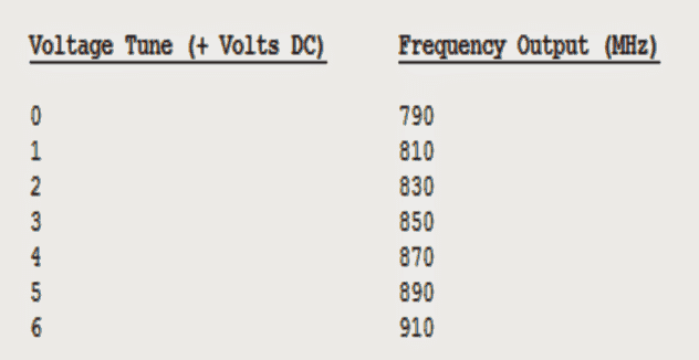
In our above discussion, a typical VCO has the ability of tuning between 790-910 MHz with a voltage tune from 0 to +6 VDC. This turns out to approximately 20 MHz of tune/volt. per volt.
Which means that, if you had the desire to "jam" the frequency ranges between 870-890 MHz, it would necessaite a +1 volt peak-to-peak triangle wave with a DC offset of +4 volts.
This might turn out to be a voltage signal sweeping between +4 and +5 VDC (referenced from ground), as well as might sweep the VCO's RF output between 870-890 MHz. Having said this,, in practically, the voltage-to-frequency mappings are not this precisely crucial..
An additional important piece of the RF jammer sequence is the end stage RF power amplifier. This might be considered as a a stage which isolates a mini RF input signal, say for example at +10 dBm (10 milliwatts), and expands it up to around +36 dBm (4 watts) and further.
The easy to get source of such amplifiers is from some discarded analog cellphones itself. Some unused old cellphones (Motorola, Nokia, Uniden, etc.) may possibly employ a broadband RF power "hybrid" module which facilitates to make their construction much hassle free and scales-down.
These types of RF module equipment are quite wideband in terms of frequency, and is designed to comfortably enlarge RF signals lying beyond their specified range. Enhancing the module's RF power control bias (Vapc) or Vdd voltage might additionally extract some more gain from these, but might also #blank# affect the expected life span of the power module. The RF power module might require to be linked with a significant, and well polished heatsink and could necessiatate a cooling fan on higher power amplifiers.
Using PF0030 RF Amplifier IC
In order to complete this project, we'll rely on a Hitachi PF0030 820-850 MHz RF power amplifier module extracted from an used or discarded CT-1055 Radio Shack/Nokia cellphone.
Such typical devices are assigned to over 900 MHz with just a nominal reduction in gain at those upper frequency rages.. Applying the Vdd voltage at +15 to +17 VDC could possibly marginally increase the accessible RF power output. I've pulled these to reach up to 10+ watts output under appropriately layed out and fixed with a large heatsink, having said this it's normally not taking the hazard situation. Press upon keeping the optimal RF output power around 5 to 8 watts.
A reasonable amount broadband RF power hybrid boards seldom make use of in excess of +13 dBm (20 mW) of RF input to run as intended to be.. It could be quite right being powerred staright from the VCO's RF output not needing any extra RF pre-amplification stage. Enhancing the RF input power might only tend to affect the life span of the power module and possibly render a nominal stress on the output gain.
Optimizing the Antenna
The crucial area of any radio technique could be the antenna. Throw generous amount of money on the antenna part (and coaxial cable), and you'll minimal hassles on your way. Rely on a coathanger and a few alligator clips and you'll be wanting to contact me millions of times a day complaining that it doesn't work.
However the good thing is, you may well dig out a reasonably good antenna from (possibly) junked analog cellphone. Those magnetic or trunk mounted antennas become compatible the best. Glass-mount antennas or some thing like that "stick-on" are traditionally a nuisance. Directional gain (Yagi) antennas could also be tried to enhance the jammer's working range, nonetheless for just in the area the antenna is directed. High-gain, omni-directional antennas may be considered very successful for most RF jamming implementations. For homebrew prototypes, you could think scaling down (or up) 900 MHz band amateur radio band antennas.
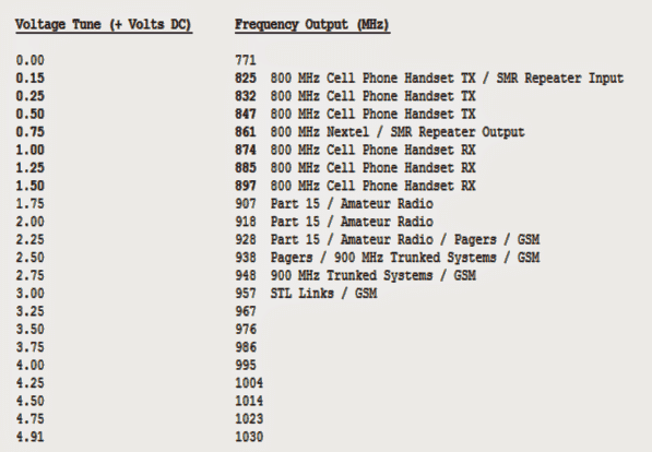
Below shown is the voltage-to-frequency mapping of Z-Comm V580MC04 VCO. The RF output power was around +8 dBm over the full frequency spectrum.
The following image shows an overview of an old Radio Shack CT-1055 (Cat No. 17-1007A) 800 MHz band analog cellular phone.
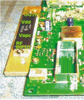
You can see the presence of the Hitachi PF0030 RF power amplifier IC module mounted over a heatsink, and ample heatsink compound being used in between the device and the heatsink. In the discussed prototype the entire IC along with the heatsink was salvaged.
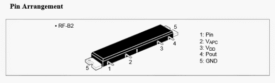
If you do not happen to have such an alanogue cellphone circuit with you, you could purchase it brand new from the market, the pinout details of the same may be witnessed below:
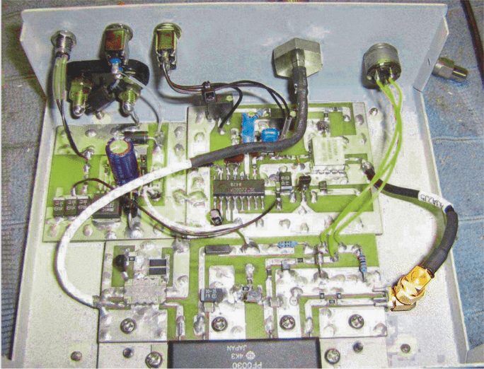
The following picture depicts an overview of the completed 800 MHz Cellular Phone Jammer unit
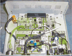
An alternate of the above may be witnessed below:
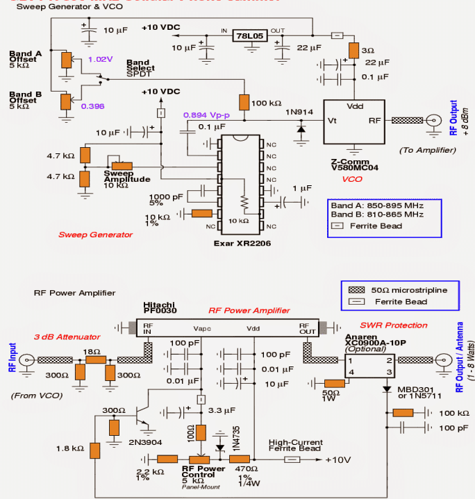
Complete circuit diagram of the above explained cellphone jammer:
(Courtesy: https://blockyourid.com/~gbpprorg/mil/celljam1/)
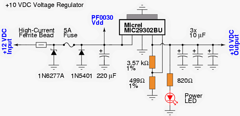
10V regulated power supply for the above cellphone jammer stages
Questions & Answers
how can i make a simple home made ccd sensor camera circuit using transistors a transmitter and make a receiver of the same signal.
works great
Hi, I am working on a mobile network jammer circuit but it hasn’t worked yet! I wanted to find out if you have done this type of project before so that you can help out.
The main thing that you must confirm is whether the jammer is actually producing the frequency matching the mobile phone’s carrier frequency. And this must be radiated in many watts through a suitable antenna. The frequency must be confirmed externally through a GHz frequency meter. Once this is correctly done, you can probably start seeing the results.
Good day sir. I was giving a project to work on gsm signal jammer. Sir your diagram is self explanatory but my confusion is that here in Nigeria we have 800, 900, 1800, 2100MHz. Sir can I get a circuit diagram of the stated frequencies above or an adjustable frequency band selector for the jammer circuit
Change the Vco.
Hi Emmanuel, This project is not mine it was referred from another website, so I am sorry I can’t suggest much for this topic
Could anyone provide a similar schematic diagram for a Wifi signal jammer with RF power output of at least 5 Watts?
sir the components are not available in the market.
and I cant understand the circuit daigram.
sir cant you tell me where i can get the components in mumbai.
yours truly,
Naman Shah
02266362452
Hi Naman, I am sorry, if the components are not available then you won't be able to build this project…in Mumbai you could try in Lamington road because that's the main electronic component hub of Mumbai and Maharashtra
sorry sir i don't understnd this artical.
baber khan
sir plz 48 v dc ka cut off circuit diagram batao? I need?
sir i have seen in other websites using antennas too.do antennas are reqired ?
reply plz.
Yasaswini, you will need a special type of antenna which were used in old mobile phones.