In bipolar junction transistors the factor that determines the sensitivity level of the device to base current, and the amplification level at its collector is called beta or the hFE. This also determines the gain of the device.
In other words, if the BJT uses relatively higher current to switch its collector load optimally then it has low β (beta), conversely if it is able to switch the rated collector current optimally using lower base current, then its beta is considered high.
In this article I will elucidate regarding beta (β) and what is hFE in BJT configurations. We will find the similarity between ac and dc betas, and also prove through formulas why the factor beta is so important in BJT circuits.
A BJT circuit in the dc bias mode forms a relationship across its collector and base currents IC and IB through a quantity called beta, and it is identified with the following expression:
βdc = IC / IB ------ (3.10)
where the quantities are established over a specific operating point on the characteristic graph.
In real transistor circuits, the value of beta for a given BJT may typically vary within a range of 50 to 400, where the approximate mid-range being the most common value.
These values provide us an idea regarding the magnitude of the currents between the the collector and base of the BJT.
To be more precise, if a BJT is specified with a beta value of 200, signifies that the capacity of its collector current IC is 200 times more the base current IB.
When you check datasheets you will find that the βdc of a transistor being represented as the hFE.
In this term the letter h is inspired from the word hybrid as in transistor hybrid equivalent ac circuit, I will elucidate more on this in our upcoming articles. The subscripts F in (hFE) is extracted from the phrase forward-current amplification and the term E is taken from the phrase common-emitter in a BJT common-emitter configuration, respectively.
When alternating current or an ac is involved, the beta magnitude is expressed as shown below:
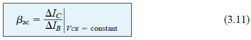
Formally, the term βac is referred to as common-emitter, forward-current amplification factor.
Since in common-emitter circuits the collector current typically becomes the output of the BJT circuit, and the base current acts like the input, the amplification factor is expressed as shown in the above nomenclature.
The format of equation 3.11 quite resembles the format of αac as discussed in our earlier section 3.4. In this section we avoided the procedure of determining the value of αac from the characteristics curves due to the involved complexity of measuring the genuine changes between the IC and IE over the curve.
However, for the equation 3.11 we find it possible to explain it with some clarity, and furthermore it also allows us to find the value of αac from a derivation.
In BJT datasheets, βac is normally shown as hfe. Here we can see that the difference is only the in the lettering of the fe, which are in lowercase compared to the uppercase as used for βdc. Here too the letter h is used for identifying the h as in the phrase hybrid equivalent circuit, and fe is derived from the phrases forward current gain and common-emitter configuration.
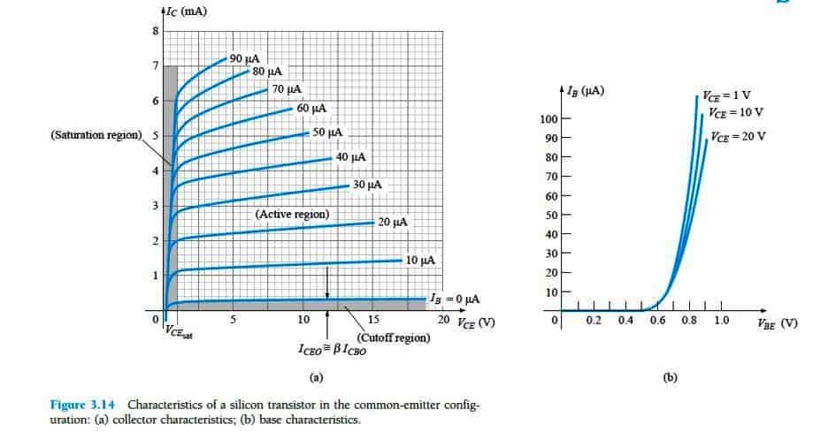
Fig 3.14a shows the best method of implementing the Eq.3.11 through a numerical example, with a set of characteristics, and this is produced again in Fig. 3.17.
Now let's see how we can determine βac for a region of the characteristics identified by an operating point having values IB = 25 μa and VCE = 7.5 V as shown in Fig 3.17.
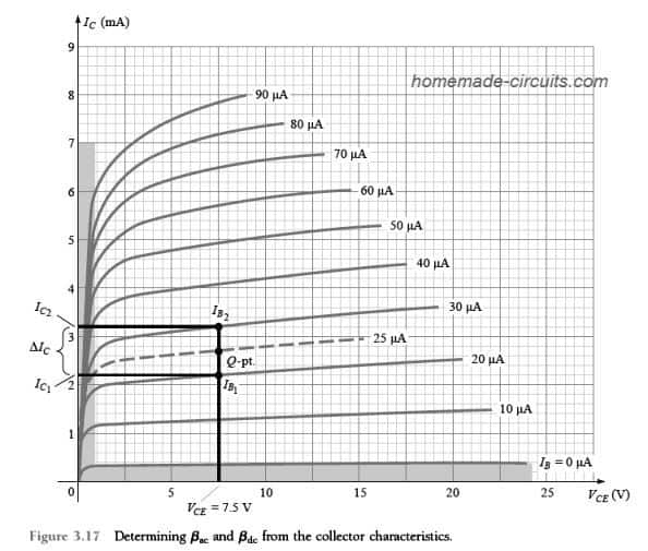
The rule that restricts VCE = constant demands the vertical line to be drawn in a way that it cuts through the operating point at VCE = 7.5 V. This renders the value VCE = 7.5 V to remain as a constant throughout this vertical line.
The variation in IB (ΔIB) as apparent in Eq. 3.11 is consequently described by selecting a couple of points on the two sides of the Q-point (operating point) along the vertical axis having approximately uniform distances on either side of the Q-point.
For the indicated situation the curves involving the magnitudes IB = 20 μA and 30 μA satisfy the requirements by staying close to the Q-point. These furthermore establish the levels of IB which are defined without difficulty instead of requiring the need to interpolate the IB level between the curves.
It might be important to note that best results is determined typically by selecting ΔIB as small as possible.
We can find out the two magnitudes of IC at the place where the two intersections of IB and the vertical axis intersect by drawing a horizontal line across the vertical axis and by evaluating the resulting values of IC.
The βac established for the specific region could then be identified by solving the formula:
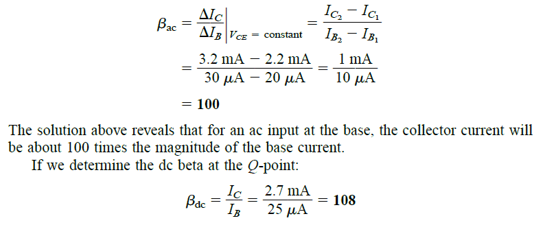
The values of βac and βdc can be found reasonably close to each other, and therefore they could be often interchanged. Meaning if the value of βac is identified, we may be able to use the same value for assessing βdc also.
However, remember that these values could be vary across BJTs, even if they are from the same batch or lot.
Typically, the similarity in the values of the two betas depends on how small the specification of ICEO is for the particular transistor. Smaller ICEO will present higher similarity and vice versa.
Since the preference is to have the least ICEO value for a BJT, the similarity dependence of the two betas turns out to be a genuine and acceptable occurrence.
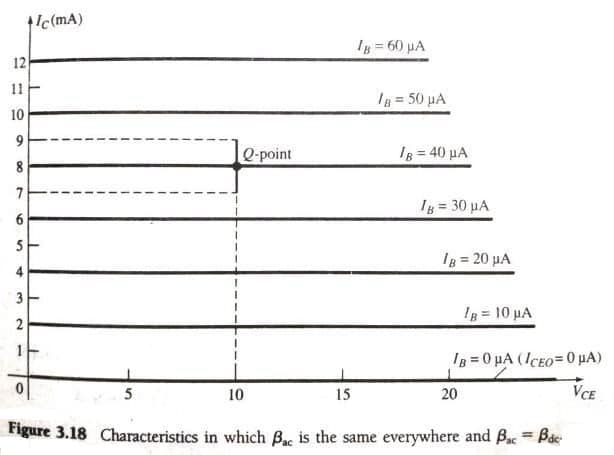
If we had the characteristic appearing as shown in Fig. 3.18, we would had the βac similar at all the regions of the characteristics,
You can see that the step of IB is set at 10µA and the curves have identical vertical spaces across all the characteristics points, which is 2 mA.
If we evaluate the value of βac at the indicated Q-point, would produce the result as shown below:
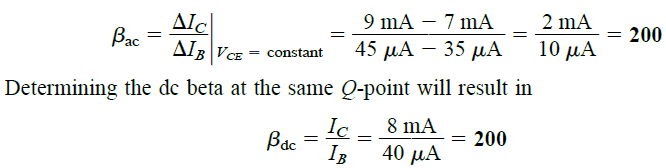
This proves that the values of the ac and dc betas will be identical if the characteristic of the BJT appear like in the Fig.3.18. Specifically, we can notice here that the ICEO = 0µA
In the following analysis, we will be ignoring the ac or dc subscripts for the betas just to keep the symbols simple and clean. Therefore for any BJT configuration the symbol β will be considered as the beta for both ac and dc calculations.
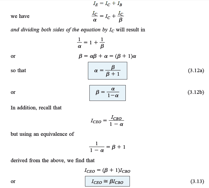
We have already discussed regarding alpha in one of our earlier posts. Let's now see how we can create a relationship between the alpha and beta by applying the fundamental principles learned so far.
Using β = IC / IB
we get IB = IC / β,
Similarly for the term alpha also, we can deduce the following value:
α = IC / IE, and IE = IC / α
Therefore substituting and rearranging the terms we find the following relationship:
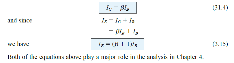
The above results is as indicated in Fig. 3.14a. Beta becomes a crucial parameter as it allows us to identify a direct relationship between the magnitudes of currents across the input and output stages for a common-emitter configuration. This can be acknowledged from the following evaluations:
This concludes our analysis regarding what is beta in BJT configurations. If you have any suggestions or further information please do share in the comments section.


Need Help? Please Leave a Comment! We value your input—Kindly keep it relevant to the above topic!