In this post I have explained a couple of interesting timer circuits customized as per individual requirements.
The first one is a kind of week/day programmable timer circuit for actuating a motor for a predetermined time only during certain selected days of the week, while the second timer circuit is for alerting a lecturer regarding the finish of the allotted time of his/her class period.
The ideas were requested by Mr. Stevan and Mr Ilman respectively.
Circuit Request#1
I spend more than 20 hours on your site, searching for a circuit I need...
My knowledge is not enough to figure which circuit I can use and I tried with many of them... If you have time, I would be very grateful if you could help me and design circuit.
I need timer circuit which will allow me to choose for how long it will stay ON (3-10 sec) and how many times it will repeat that action during 7 days (1-7 times i.e. once in a week, twice in a week, every day etc). I need it for controlling 9-12V electrical motor.
Circuit Diagram
Circuit Operation
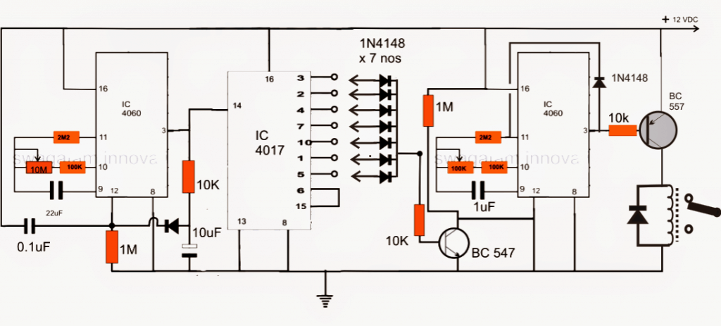
As shown in the above week day programmable timer circuit, the IC 4060 at the left side is wired up as a 24 hour timer circuit.
The time length is determined by the 22uF capacitor and the 10m pot. A suitable fixed value may be selected for these two components for getting the specified time delay.
The 22uF capacitor must be non-polar low leakage type of capacitor and the resistors should be MFR 1%
The output is received from pin#3 of the above IC, which goes high as soon as the set time elapses. This results in a short pulse to pin#14 of the IC 4017 which is configured as a 7 stage counter divider here.
With every pulse after the preset 24 hours interval, the IC 4060 also resets itself via the diode connected across its pin#3 and pin#12.
The IC 4017 output functions as a week timer where its 7 outputs shift (become high) from pin3 to pin6 sequentially in response to the above 24 hour pulses, depicting the 7 days of the week.
The right hand side IC 4060 is configured as short duration timer for activating the motor which may be connected with the shown relay contacts.
This stage is integrated with the IC 4017 stage through the shown 7 1N4148 diodes. Depending on what days the motor needs to be switched ON, only those relevant diodes are connected with the 4017 outputs, rest of the diodes are kept unconnected.
After all these connections, when power is switched ON, the left hand side 4060 triggers and forces the outputs of the IC 4017 to become high in sequence every after 24 hours.
Depending upon the connections of the diodes, the right hand side 4060 IC gets switched ON only on those selected days of the week via the BC547 transistor which grounds its reset pin#12 on receiving the signal from the IC 4017 relevant outputs.
This prompts its pin#3 to go low activating the preceding relay driver stage and the motor.
The above stage stays activated until the set time elapses when its output becomes high inhibiting the relay driver sage from base drive thereby stopping the motor.
The high from the pin 3 also latches the IC via the diode to its pin11. The time interval may be fixed by adjusting the given 100k pot
The whole operation resets on the next pulse from the 24 hour 4060 timer stage.
The operation thus repeats as per the programming done on the three ICs.
Circuit Request#2
I need circuit for time limiter to use for public speaking.
Say if a teacher has one hour to speak in the class then the timer will show a green light starting from 60 minute then counting down to 0, but before finish the yellow light will turn on to remain a teacher that the time almost finish, it can be 3 minutes before to 0, finally when the time is over the red light will be on, it means that time for the teacher is finish.
Circuit Operation
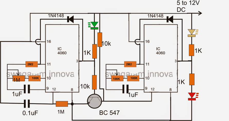
The above cascaded two stage sequential timer circuit is rather simple with its configuration Two 4060 ICs are linked with each other to form a sequential timer configuration.
The left IC is rigged as a 57 minute timer circuit while the right hand side IC as a 3 minute timer circuit.
When switched ON the left IC starts counting (green LED ON) until 57 minutes have elapsed which makes its pin3 go high, shutting off the green LED
This triggers the connected BC547 transistor which now grounds pin12 of the second 4060 IC prompting it to start its 3 minute counting process.
This activates the yellow LED indicating the last 3 minutes being counted, until it gets over shutting off the yellow LED and switching ON the RED LED.
The diodes across pin3 and pin11 of the ICs keep the ICs latched until the circuit is switched OFF and switched ON for initiating the next cycle.
Using LDR for Detecting Day Night Periods
The fundamental strategy is to produce an electronic signal that turns high once the sun sets and turns low as dawn sets in, followed by counting the transitions. Photocel1 LDR1 is positioned to sense the sun light.
This must be targeted at the north skies instead of the sun directly, thus it is going to see practically the same thing during clear skies and also over cast ones.
R1 is placed for controlling sensitivity of the LDR.

A good way to fine-tune it, without dealing with a complete day/night period, is to hold off until around 10 minutes following sunset, at the center rotation between day and night, and alter R1 in order that the voltage across it is half the supply voltage.
Later, examine that the IC1 output is high during night and low during the daytime. A low-pass filter is created using R2 and C1, producing roughly a 1-second hold up to ensure the circuit doesn't get rattled with lightning flashes or various other brief light variations.
A 555 timer, ICI, is employed like a light level sensor; instead of the comparator circuit. The 555 offers hysteresis, which implies that the trigger ON voltage will be greater than the trigger-off voltage.
This prevents the circuit from "stuttering" to and fro between off and on during transition thresholds. The second IC in the circuit (IC2) is a 4017 (CD4017) CMOS decade counter.
Simply by hooking up output Q8 to the reset input, we allow it to count upto 7 and then start off yet again, therefore its output creates a solitary day-long pulse each week. You are able to supply this to additional counters in order to calculate even extended time periods.
For instance, incorporating a divide-by-four counter (like a 4017 with Q5 attached to reset) could give you a period of 28 days.
7 Day ON and 7 Day OFF Timer Circuit
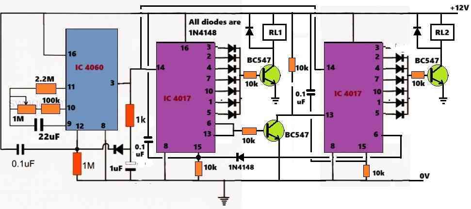
The following circuit will keep relay#1 switch ON for 7 days, and when relay#1 is switched OFF after 7 days, relay#2 is switch NN for the next consecutive 7 days. This alternate 7 day ON and 7 day OFF across relay#1 and relay#2 is maintained infinitely, as long as the circuit remains powered ON.


Questions & Answers
thank you sir, this is the link which you suggest me….and its working fine,

thanks you sir, sir at ic 4017 output positive of led connected output pin and at negative of led need 1k resister or no need?
Thank you sir, its done
Thank you Ghulam! Glad to know the LEDs are working..
Hi Ghulam, Resistor is not required, because the resistor is already present at the BC547 base…
Thanks Ghulam,
For LED indication, you can just add an LED in series with each of the 1N4148 diodes (between 4017 output pin and 1N4148 anode), across all the shown 4017 IC outputs.
If you find the LED light is low, you can change the BC547 10k resistor to 4.7k or 2.2k or maybe 1k
Please, I need a timer circuit that runs approximately 5 seconds and separates for 2 hours repeatedly without my intervention. It is used to stir eggs in the incubator, with the possibility of adjusting the separation time by increasing or subtracting some seconds. Thank you to everyone, wonderful people.
Hi, you can try the following concept and adjust the timing components according to your needs:
https://www.homemade-circuits.com/how-to-make-simple-programmable-timer/
I want 18 days countdown days circuit.
Hello sir
Hope all is going well with you and your familly.
Reqested diagram for timer change over. I want to make timer change over for two electric input and 1 output (like load). I want that 1st source should be on for 7days after that automatically switched off first source and switched on 2nd source.for 7 days. Like this sequence work automatically. Please provide me circut diagram
Please support me as you are always giving kind response.
Thanks
Hello Ghulam,
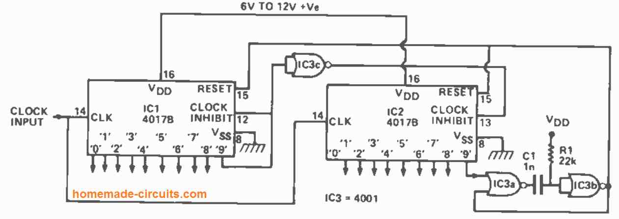
You will have to build it step-wise. First build the following cascaded 4017 sequential driver, then build 2.4 hour clock generator and after that the driver stage:
I will try to update the complete diagram soon in the above article.
Please sir i am thank full to you. As soon as possible plz share the complete diagram with components, and as last i discused with you i am learner so plz provide me diagram in easy way like cd4060 project on and off circut.
Thanks
Ghulam, the 4060 ic or any other single ic cannot be used to create 7 day long on/off cycles, so the circuit will be difficult using many cmos ics.
The above circut is with cd4060 and cd4017. Like this if we make 2 circuts and then with transister can we reset auto as my requirement. Plz sir try to guide me.
Yes that’s possible but if you adjust the 4060 IC to produce 24 hour long delay, its accuracy can be affected by maybe by 5 or 10%…then for 7 days this fault can aggravate to produce a difference of many hours within 7 days.
Sir i will try if you provide me complete circut diagram with auto reset option plz
Ghulam, I will design it and let you know soon.
thank you so much
Ghulam, what should be the output switching device be, should there be two relays, relay#1 and relay#2? Relay#1 will be ON for 7 days, then it will switch OFF and Relay#2 will switch ON for the next 7 days, and the cycle will repeat? Let me know if that will do or not?
Exactly same i want plz. With 2 relays with same 7 days seqanc on and off…I will be thank full to you for your kind support.
OK, I have designed the circuit for you, please check it out in the following link:
Sir a lot of thanks. I will try and update you as soon as possible, once again thank you very much
Ghulam, in the previous diagram which I suggested you, i have made some modifications around the pin#15 of IC 4017…please check all the components connected with pin#15 of the two 4017 ICs and do the same in your prototype.

Hi sir, first of all i want to say thanks from heart, today i assembled and its working fine, for testing i connected pin 7 of cd4060. And RL1 on for 8 mints, but the problem is other relay on for almost 7.13 mints. I think in ic1 4017 you connected diode with pin no 3,2,4,7,10,1,5 but 2nd ic 4017 you didnot conent pin 3, may be due to this time is less, plz check and update me, i will connect .1uf with pin 15 of 4017, thanks for update me.
A lot of thanks
Thank you Ghulam, I will try to solve the issue.
The pin#3 of IC 4017 is HIGH by default when the circuit is powered On and in reset mode. Meaning when the circuit is powered ON pin3 of both the ICs will be HIGH.
That means if the pin#3 of the second 4017 IC is connected with its Bc547 base, Relay1 and relay2 both will be ON initially when circuit is powered On, which we don’t want, we want only the RL1 to switch ON initially, and RL2 to remain switched OFF.
Now the question is, when the left side 4017 completes its 7 day and toggles the second IC 4017, is the relay2 switched ON immediately during this changeover?
If the above changeover from relay1 to relay2 is happening instantly, then it is fine, and we can add pin#6 in the line for the second IC 4017 and try to adjust its timing to 8 minutes.
Let me know your thoughts on this.
Sir what you changed i did. Like 0.1uf connected to pin 15 to positive of both ics, and diode is connected with 2nd ic 4017 pin 6 to 1st ic 4017 pin 15. I did this but 1st relay continuesly on. Timing for testing i am using cd4060 pin no 7, before was working, timing little bit diffrence no issue, i am finding you disconnected 10k from 2nd ic pin 13 to positive, is it? Please make sure where is the problem after connected update diagram.
Also i got it your point to 8 mints, that is fine, off cource we need to on 1 relay first. So that is ok.
Plz solve now for update diagram, 1st relay continuesly on…
The 10K from pin#13 of the 2nd 4017 is mistakenly cut, please join it, it should be connected.
Now, the left side 4017 relays, you are saying is permanently ON, this can happen only when its pin#15 is permanently connected with the positive line.
Make sure your pin#15 0.1uf capacitor is good. Or try disconnecting the 0.1uF at pin#15 temporarily and check again.
Hi sir,
Extremlly sorry to disturb you again Sir before updated circut it was working. While i connect update points after that not working even i removed 0.1uf from both ics, may be some where short circut. I will try again but from your side please re-check once again and update me final diagram with led connection which shows days indication with cd4017 as i discussed earlier, then i will try again, because after removing 0.1uf first relay ic 4017 goes heat.
Thanks
Hi Ghulam,
The 0.1uF between pin15 and positive are required to ensure the IC always resets when power is switched ON and its outputs always start from pin#3.
We do not want the output to start from any random output pin other than pin#3, right? that is why 0.1uF capacitor at pin#15 is important.
I have rechecked pin#15 connections, it is perfectly correct.
IC 4017 can heat up only under the following conditions:
Supply input is higher than 15V.
Output pins shorted to ground.
IC is faulty or duplicate.
Please check your circuit confections. Are you using breadboard? then there might a chance of some loose connections maybe.
Thanks for always kind reply, sir i am using 12volt supply, and makeing circut on zero board, yea may be there is short circut, i will make it again with new update,
No problem Ghulam, please let me know!
Hi sir,
Dear sir i want to clear about diode which is connected cd4060 pin 12 to 1uf positive, with 1 k resister which goes to cd4017 pin 14,that connection with cd4060 12 pin or 11?
Thanks
Hi Ghulam, the diode which you are referring to is connected to pin#12 of 4060.
There is another diode connected to ic 4017 pin#15, please note that this diode is not joined with bc547 emitter…it is mistakenly shown as joined to bc547 emitter.
Acha sir its update to you, 1st relay shifted to 2nd relay while again 1st relay on. Its stuck…..after main power off and again on its works for 1 time. What changes required to auto shifted to rly1 and rly2 plz this cycle want to continue plz
No problem Ghulam, I appreciate your hard work and efforts.
As you can see, the pin6 of the 2nd 4017 ic is connected with pin15 of the 1st 4017 IC, why this is done?
This is specifically done so that when 2nd 4017 sequence reaches the last pin6, it’s output hits the pin15 of the 1st 4017 and RESETS it. So each time the 2nd 4017 finishes its timing sequence it resets the 1st 4017 ic so that the whole circuit resets and starts from beginning.
So the 1st 4017 should start afresh as soon as the 2nd ic finishes its timing sequence and should not get latched.
I will try to draw a new diagram to show a few LED connections which will indicate the sequencing procedure and let you understand the working sequence of the 2 ics.
Sir i want both ics automatically reseted…..its only for one time reset. As i write you before. Plz give me soltuion with thanks
Ghulam, the second IC must also reset when the 1st IC resets because the pin#13 of the 2nd Ic becomes high when 1st IC resets.
You can do one thing, connect another 1N4148 diode at pin#6 of the second 4017 IC and connect it with pin#15 of the 2nd 4017 IC.
Without LED indications you will not be able to understand the sequence pattern.
Sir i am not using leds, only relay on led using…..which side need to be connect with 2nd ic pin#6 and pin# 15 (in4148)or may be its due to diode which is connected with 2nd ic pin 6 to 1st ic pin 15. If we remove and connect without diode. Can be possible reseted automatically both relays.
Ghulam, If you remove that diode then the 0.1uF capacitor will come in direct contact with pin#6 which is not good, and the IC will not reset at power switch ON.
You can see one 1n4148 diode is already connected from pin#6 of 2nd IC to pin#15 of the 1st IC.
Now, connect another 1N4148 diode between pin#6 of SECOND IC and pin#15 of the SECOND IC.
That means, one 1N4148 going from pin#6 of 2nd IC to pin#15 of the 1st IC, and another 1N4148 going from the pin#6 of the 2nd IC to pin#15 of the second IC.
Yes sir I got it your point. I will try and update you as soon as possible. Thanks
Sure, let me know if you have any further problems.
One thing more i want to know, input voltage from 12 volt lithum battery with bms is ok for this circut? For charging battery solar is good or 12 volt 1 or 2 amp supply is best?
The DC 12V can be from any source, a battery or a power supply, not an issue.
Charging supply can be from any constant DC source, it can be from a solar panel or a 12V power supply. Charging current will depend on the mAh value of the battery.
Hi sir, hope all is going well. Sir i want support related changeover project, with cd4060 and 4017, i am facing one issue, while short circut ic cd4017 is demaged and that time both relays on same time, in this situation load creating problem, can you guide me any way to stop voltage goes to relays in case of one ic demage plz.
I am using 12 volt batery to keep on circut and memory for timer, while electricity goes off.in this case for charging i am using smps, once smps have any issue then ic cd4017 demaged i dont why, even i am using 3s bms 20a as well,
Plz guide me soltuion….
Hi Ghulam, if your IC gets damaged then the whole circuit will malfunction, there’s no way to solve this problem. Firstly your IC should not get damaged under any circumstances. You can ensure this by using good quality ICs and a regulated DC for powering the circuit. You can also connect a 100uf and 0.1uf capacitor right across the ic 4017 and ic 4060.
Sir i need your one more support plz, can you provide me garber file for pcb for complete circut plz
Ghulam, Sorry, designing the PCB can take a lot of time so it may not be possible for me. You will have to get it designed from a PCB specialist.
No problem sir i will try to manage. A lot of thanks
Yea sir i have done, its working as per my requirement, a lot of thanks
Sir i need more help about human body sensor, its default on time is 2 sec, please guide me how i can increase the on time . I add 1 uf capister its giving almost 2 minuts but its not proper solution. Plz guide me or if possible give me diagram plz
Thanks Ghulam, Glad it is working now!
Are you referring to a PIR sensor?
You will have to adjust the preset to adjust the delay, as explained in the following article:
https://www.homemade-circuits.com/pir-sensor-datasheet-pinout-specification-working/
For further discissions on this, please comment under the above PIR article.
Hi sir, i am thankfull to you. I dont have words to say thanks. You are good teacher and have amazing passion. i checked now its working fine, with these values which is connected with cd4060 while 500k is low state its shifted in almost 2.5 mints, and the end state of 500k its almost 10 minuts.
Sir i connected 12 volt 30a relay with this circut, after that i will connect 1 relay which is ac 220v relay with 120A. Hope it will work with powerfull changeover….if you have any idea to make strong please suggest me. A lot of thanks
Noted…thank you sir
Please also note that the pin#6 of the 2nd 4017 IC connects with the 1N4148 anode.
In the diagram pin#6 seems to be joined with BC547 emitter that is a drawing mistake, please correct that.
pin#6 of the 2nd 4017 IC directly connects with the anode of 1N4148 and the cathode of 1N4148 connects with the pin15 of the 1st 4017.
No problem Ghulam, all the best to you!
Sir where we can use 6 leds for days complete status with 1 k before diode or after diode?
Ghulam, you can put series leds at the anode side or at the cathode side of the diodes, it does not matter.
Hi sir,
Hope all is going well. Sir i need some information about changeover project, sir i want to use 100a ssr da, for high load, i want to know can i gve connection from transister bc547 directly to ssr, or i have to connect normal relay 12volt 10a, and from relay positve and neagtive give to ssr?hope you understand my point. Also waiting for with led connection circut digram plz
Thanks
Hi Ghulam,
A BC547 can be used to drive the input of an SSR, because SSRs require very low input signal to switch ON.
For the LED connections for your 24 hour week ON OFF circuit, you can simply connect the LED in series with the 4017 output diodes. You can also connect LEDs in series with the bases of the BC547 transistors.
hi sir, first of all i want to inform you that changeover circuts which i made with the kind help of you that is working perfectly since last year, thank you for your support. sir i want to upgrade with leds as i discussed with you before. plz provide me digram with leds with diods in series plz
That’s great Ghulam, glad it is working nicely for you!
Can you please show the diagram link which I had suggested you….I will try to upgrade it LEDs, and let you know soon…
Thank you sir
Sir, I thank you for what you have given us, but I want a timer circuit that starts the engine for 20 minutes and stops it for 25 minutes, while repeating this process for 24 hours without interference. Is it possible to add a screen or indicator for the number of times it is started and stopped? Thank you very much.
Thank you Khaled,
I think you can try the following design for implementing the desired application:
https://www.homemade-circuits.com/how-to-make-simple-programmable-timer/
For the counter you can add the following design with the above timer:
https://www.homemade-circuits.com/5-digit-frequency-counter-circuit/
Hi sir thanks for share with us good topic. I want to make timer on and off automatically, suppose i want to switvh on my load for 12hrs and off for 5 hrs what i have to do? Plz suggest in easy way, this cycle auto work daily.plz send me diagram with bc547 pinout and comopnent plz
Thank you, Ghulam,
You can try the following circuit concept for fulfilling your requirement:
https://www.homemade-circuits.com/how-to-make-simple-programmable-timer/
Hello,
Thank you very much, the first circuit is perfect for a project I am working on. I’m relatively new to circuits and I wanted to try to understand what is happening a little more. Could you explain the purpose of some of the components for me?
How does the 10M pot change the calculations for the frequency for the 4060? Every time I try to use the formula you gave in the 4060 explained article, either to calculate the frequency from what you gave or try to calculate the resistance from the frequency I want, my answers never match up.
What is the purpose of the diode across pin#3 and pin#12? When I was looking through that 4060 article, it didn’t seem like a diode was necessary, is it still?
What is the purpose of the 10 uF polar capacitor between pin#3 and the ground?
Sorry for all the questions, I’m just hoping to learn more.
You are welcome, and appreciate your feedback.
The 10M forms the timing resistor for the complementing timing capacitor Ct. The Ct is charged and discharged alternately via Rt with the help of the actions of the IC internal gates connected with the Rt, Ct.
In the formula you must use Ct in Farads, and Rt in Ohms.
The diode causes instant resetting and reverting pin#3 to zero so that the next count is able to start from a perfect zero, and this ensures accurate uniform timing pulses from the IC 4060.
The capacitors ensures that pin#14 gets a proper logic from pin#3 and the IC 4060 is erset after some delay, allowing pin14 of the IC 4017 to implement the changeover correctly.
las publicaciones son excelentes,por lo básicas que son ,me han ayudado a comprender el funcionamiento de muchos aparatos electrónicos y mecánicos de la manera mas simple,por lo que esto me permitido poder interpretar planos y maquinas mas complejas.
bueno no puedo escribir muy bien Ingles pero si pudo traducir perfectamente.
¡Gracias! Realmente aprecio sus pensamientos y me alegro de que le hayan gustado mis artículos, ¡sigan con el buen trabajo!
Love all your work!
Such blessing to many.
Old ET. From tubes to transistors and ICs.
Enjoying everything.
Walt. S.
Thanks a lot, Glad you liked my work, please keep up the good work!
Would love to see a circuit that turns an LED on for 4 hours, then sleeps for 20 hours. Part of my adventures in making an LED candle setup.
You can probably try the following design:
https://www.homemade-circuits.com/how-to-make-simple-programmable-timer/
For the 20 hour stage in the circuit use many 1uF non-polar cps in parallel for C1
Dear Swagatam Majumdar
Im Shouquat. I like ur work. May I know, How to check the 7 days daily circuit? Its working or not. Because if its working but wait for long time to see the result. Can u give me some idea to check the circuit quickly? Regards,
Respected Sir,
I love your blog. I spend a lot time for searching circuit for countdown timer switch for 120v but I cannot find it. Can you please upload one or can guide me for the same?
Thank You
shah
kristin, please provide more details about your requirement, i'll try to help.
Thanks Guru …
It works by little bit correction in pin 8 (IC2) should be opened from ground.
My next question is about the formula for resistors and capacitor that connect to pin 9 and 10, so I can calculate the time needed.
Thanks for your help.
Gumilar
Gumilar, if you disconnect pin8 of any of the ICs will result in malfunction of the circuit, because it's the ground pin of the ICs.
For the formula you may refer to this article:
https://www.homemade-circuits.com/2012/01/how-to-make-simple-versatile-timer.html
Dear Swagatam, thank you very very much for this circuit, explanation and your time! I have just two additional question…
You wrote "Depending on what days the motor needs to be switched ON, only those relevant diodes are connected with the 4017 outputs, rest of the diodes are kept unconnected" – Does it mean that motor can be turned ON for example 2nd day and 4th day?
My second question is about +12V and Ground because it looks like it's short circuited?
Thanks again…
Dear Stevan,
Thanks! Yes the motor can be switched ON on any particular selected days of the week.
I have corrected the diagram, the short is removed now.