A triac can be compared to a latching relay. It will instantly switch ON and close as soon as it's triggered, and will remain closed as long as the supply voltage remains above zero volts or the supply polarity is not changed.
If the supply is an AC (alternating current), the triac will open during the periods the AC cycle crosses the zero line, but will close and switch ON as soon its re-triggered.
Advantages of Triac as Static Switches
- Triacs can be effectively replaced for mechanical switches or relays for controlling loads in AC circuits.
- Triacs can be configured to switch relatively heavier loads through minimal current triggering.
- When triacs conduct (close) they do not produce debounce effect, as in mechanical switches.
- When triacs switch OFF (at AC zero crossing), it does this without producing any transients, due to back EMFs etc.
- Triacs also eliminate fusing of contacts or arcing issues, and other forms of of wear and tear which are commonly seen in mechanical based electrical switches.
- Triacs feature a flexible triggering, which allows them to be switched at any given point of the input AC cycle, through a low voltage positive signal across gate and common ground.
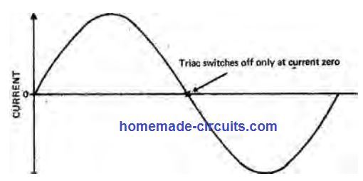
- This triggering voltage could be from any DC source such as a battery or a rectified signal from the AC supply itself. In any case, the triac will go through switch OFF periods whenever each half cycle AC waveform moves through the zero crossing (current) line, as depicted below:
How to Switch-ON a Triac
A triac consists of three terminals: Gate, A1, A2, as shown below:
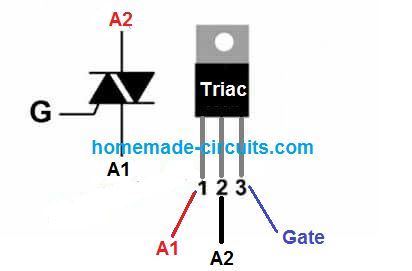
To switch-on a Triac, a gate trigger current must be applied on its gate pin (G). This causes a gate current to flow across Gate and terminal A1.
The gate current could be positive or negative with respect to A1 terminal of the triac. A1 terminal may be wired in common to the negative VSS line or positive VDD line of the gate control supply.
The following diagram shows the simplified schematic of a Triac and also its internal silicon structure.

When a triggering current is applied to triac gate, it is switched ON by means of its inbuilt diodes embedded back-to-back between G terminal and and A1 terminal. These 2 diodes are installed at the P1-N1 and P1-N2 junctions of the triac.
Triac Triggering Quadrants
Triggering of a triac is implemented through four quadrants depending on the polarity of the gate current, as shown below:
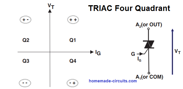
These triggering quadrants can be practically applied depending on the family and the class of the triac, as given below:
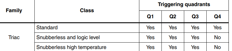
Q2 and Q3 are the recommended triggering quadrants for triacs, since it allows minimal consumption and reliable triggering.
Q4 triggering quadrant is not advised as it calls for a higher gate current.
Important Triggering Parameters for Triacs
We know that a triac can be used to switch high power AC load across its A1/A2 terminals through a relatively small DC trigger supply at its Gate terminal.
While designing a triac control circuit, its gate triggering parameters become crucial. The triggering parameters are: triac gate triggering current IGT, gate triggering voltage VGT, and gate latching current IL.
- The minimum gate current required to turn on a triac is called gate triggering current IGT. This needs to be applied across the gate and the A1 terminal of the Triac which is common to the gate trigger supply.
- The gate current should be higher than the value rated for the lowest specified operating temperature. This ensures optimal triggering of the triac under all circumstances. Ideally the IGT value should 2 times higher than the rated value in the datasheet.
- The trigger voltage applied across the gate and the A1 terminal of a triac is referred to as VGT. It is applied through a resistor which will discuss shortly.
- The gate current that effectively latches a triac is the latching current and is given as LT. The latching can happen when the load current has reached the LT value, only after this the latching enables even while the gate current is removed.
- The above parameters are specified at an ambient temperature of 25 °C, and may stat showing variations as this temperature varies.
Non-isolated triggering of a triac can be done in two basic modes, the first method is shown below:
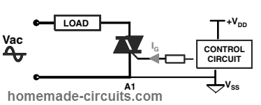
Here, a positive voltage equal to the VDD is applied across the gate and A1 terminal of the triac.
In this configuration we can see that the A1 is also connected to the Vss or the negative line of the gate supply source. This is important otherwise the triac will never respond.
The second method is by applying a negative voltage to the triac gate as shown below:
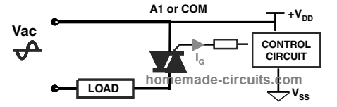
This method is identical to the previous except the polarity.
Since the gate is triggered with a negative voltage, A1 terminal is now joined in common with the VDD line instead of Vss of the gate source voltage. Again, if this is not done, the triac will fail to respond.
Calculating the Gate Resistor
The gate resistor sets the IGT or the gate current to the triac for the necessary triggering. This current increases as the temperature drops below the specified 25 °C junction temperature.
For example if the specified IGT is 10 mA at 25 °C, this may increase up to 15 mA at 0 °C.
To ensure that the resistor is able to supply sufficient IGT even at 0 °C, it must be calculated for the maximum available VDD from the source.
A recommended value is around 160 to 180 ohms 1/4 watt for a 5V gate VGT. Higher values will also work if your ambient temperature is rather constant.
Triggering through External DC or Existing AC: As shown in the following figure, a triac can be switched either through an external DC source such as battery or solar panel, or an AC/DC adapter.
Alternatively, it can be also triggered from the existing AC supply itself.
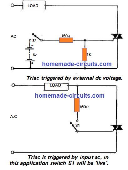
Here, the switch S1 has negligible stress on it since it switches the triac through a resistor causing minimal current to pass through the S1, thus saving it from any sort of wear and tear.
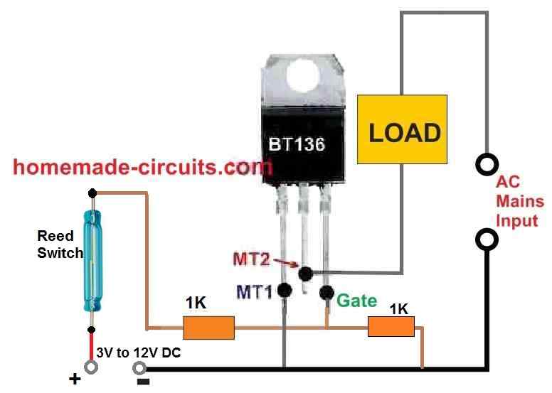
Switching a Triac through a Reed Relay: For switching a triac by a moving object, a magnetic based triggering could be incorporated.
A reed switch and a magnet can be used for such applications, as shown below:
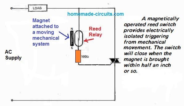
In this application the magnet is attached to the moving object. Whenever the moving system gets past the reed relay, it triggers the triac into conduction through its attached magnet.
Reed relay can be also used when an electrical isolation is required between the triggering source and the triac, as shown below.
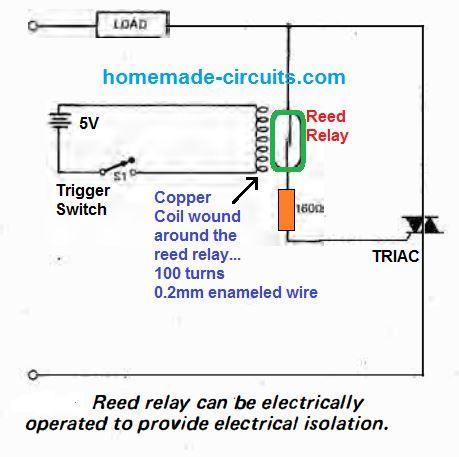
Here, the copper coil of suitable dimension is wound around the reed relay, and the coil terminals are connected to a DC potential via a switch.
Each time the switch is pressed causes an isolated triggering for the triac.
Due to the fact that reed switch relays are designed to withstand millions of ON/OFF operations, this switching system becomes extremely efficient and reliable in the long run.
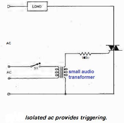
Another example of isolated triggering of triac can be seen below, here an external AC source is used for switching a triac through an isolation transformer.
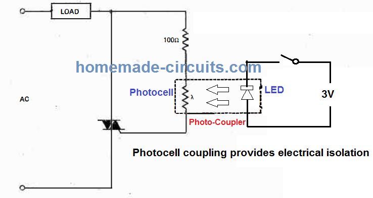
Yet another form of isolated triggering of triacs is shown below using a Photo-cell couplers.
In this method an LED and a photo-cell or photo diode are integrally mounted inside a single package. These opto couplers are readily available in the market.
An unusual switching of the triac in the form of off/half-power/ full-power circuit is shown in the diagram below.
To implement 50% less power the diode is switched in series with the triac gate. This method forces the Triac to switch ON only for the alternate positive AC input half-cycles.
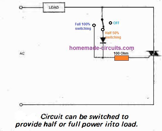
The circuit can be effectively applied for controlling heater loads, or other resistive loads having thermal inertia.
This might not work for lighting control, since the half positive AC cycles frequency will result in an annoying flicker on the lights; likewise, this triggering is not advised for inductive loads such as motors or transformers.
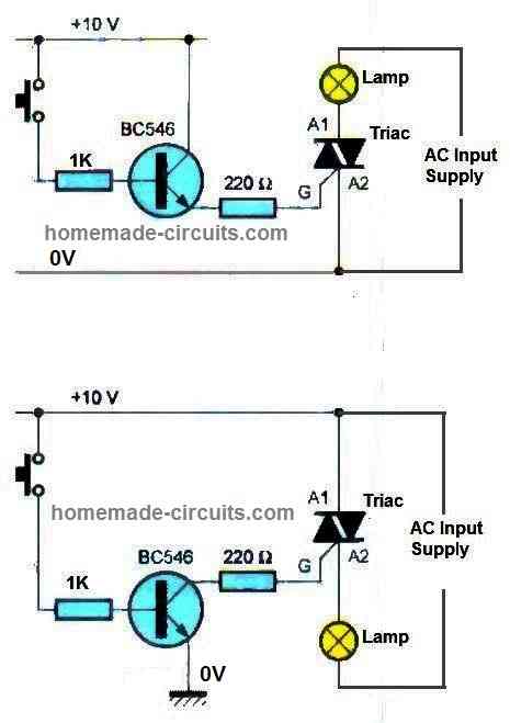
Set Reset Latching Triac Circuit
The following concept shows how a triac can be used for making a set reset latch using a couple push buttons.
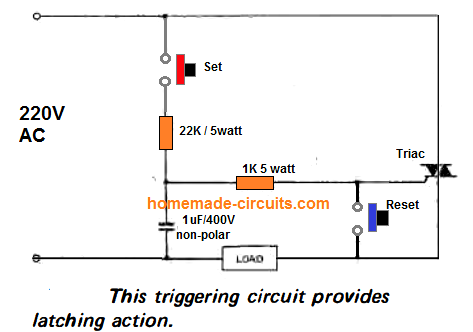
Pressing the set button latches the triac and the load ON, while pressing the reset button beaks the latch.
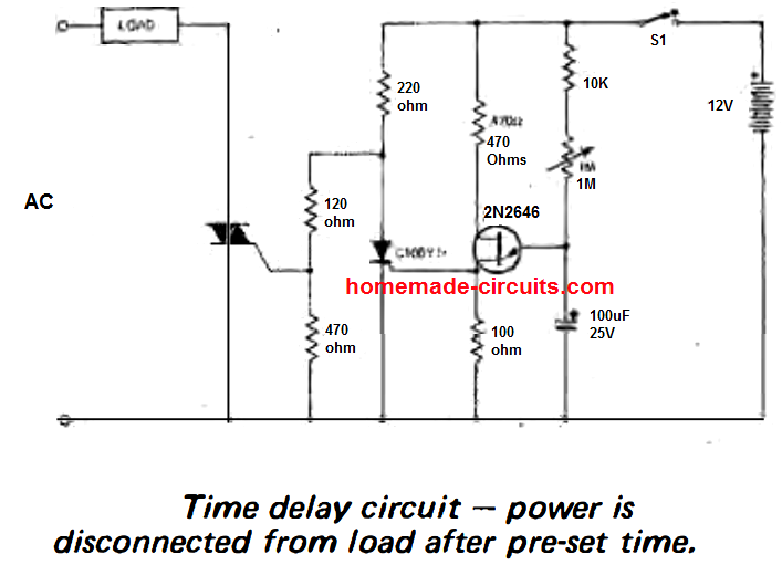
Triac Delay Timer Circuits
A triac can be set up as a delay timer circuit for switching a load ON or OFF after a set predetermined delay.
The first example below shows a triac based delay OFF timer circuit. Initially when powered, the triac will switch ON.
In the meantime the 100uF begins charging, and once the threshold is reached the UJT 2N2646 fires, switching ON the SCR C106.
The SCR shorts the gate to ground switching OFF the triac. The delay is decided by the 1M setting and the series capacitor value.
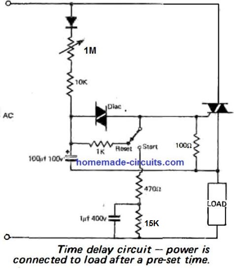
The next circuit represents a delay ON triac timer circuit. When powered the triac does not respond immediately. The diac remains switched OFF while the 100uF capacitor charges to its firing threshold.
Once this happens the diac fires and triggers the triac ON. The delay time depends on the values of 1M and the 100uF.
The next circuit is another version of a triac based timer. When switched ON, the UJT is switched via the 100uF capacitor.
The UJT keeps the SCR switch OFF, depriving the triac from the gate current, and thus the triac also remains switched OFF.
After sometime depending on the adjustment of the 1M preset, the capacitor is fully charged switching OFF the UJT. The SCR now switches ON, triggering the triac ON, and also the load.
Triac Lamp Flasher Circuit
This triac flasher circuit can be used to flash a standard incandescent lamp with a frequency that may be adjusted between 2 and about 10 Hz.
The circuit works by rectifyingthe mains voltage by a 1N4004 diode along with an variable RC network.
The moment the electrolytic capacitor charges upto the breakdown voltage of the diac, it is forced to discharge through the diac, which in turn fires the triac, which results in flashing of the connected lamp.
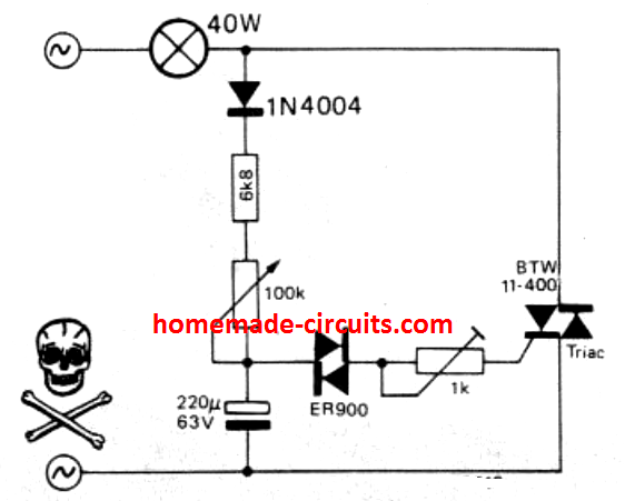
After a delay as set by the 100 k control, the capacitor recharges again to cause a repetition of the flashing cycle. The 1 k control sets the triac triggering current.
Additional Information about Triacs
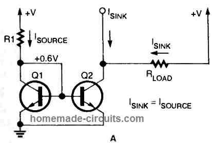
Before moving on to the triac, it is appropriate to recall some principles regarding the thyristor, which is a semiconductor consisting of four layers of silicon alternately doped positively and negatively (PNPN).
To to make it simple, imagine couple of transistors, an PNP and an NPN configured in a way as shown in the following figure.
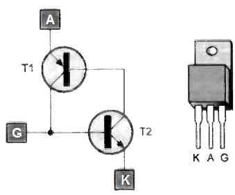
As long as no current flows between G (gate) and K (cathode), the thyristor is blocked.
By establishing a current between the gate and the cathode, transistor T2 saturates, allowing the "flow" of a current between the emitter and the base of transistor T1.
The latter saturates in turn. Therefore, T2 continues to be saturated even when no positive potential is presented to the gate. Indeed, it is transistor T1 that takes over by maintaining the "flow" between the base and emitter of T2.
In the end, there is self-maintaining conduction of the thyristor. This situation persists until the AK current circulation has been interrupted.
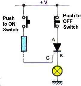
The following figure describes the operation of the thyristor. When you press the "on" button it lights up the bulb, when you press the "off" button, it causes the lamp to turn off.
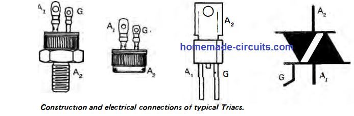
Constitution of a triac
Still for the purpose of simplification, we will assume that the triac is equivalent to two thyristors connected in a back-to-back manner.
Therefore, unlike the thyristor, which is a unidirectional component, the triac is bidirectional. Its use in applications involving alternating current then becomes evident.
The next figure below illustrates, in a very schematic way, the internal structure of a triac.
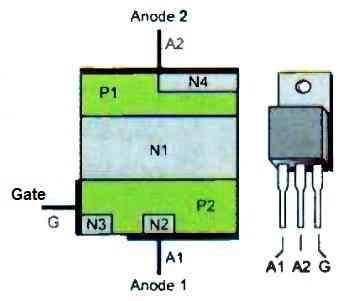
Note that it also has three electrodes - two main electrodes referenced as A1 and A2 - and a control electrode also called the "gate".
On the same figure, identify the two thyristors that make up the triac:
N4/P1/N1/P2 -
P1/N1/P2/N2.
Triac triggering control
In theory, the triac becomes "on" between A1 and A2 when the potential between these two electrodes becomes higher than a given value.
The application of a potential on the gate results in a very significant decrease in this breakdown voltage.
This is true regardless of its polarity.
Theoretically, this results in four modes of presenting the gate potential relative, for example, to the A1 anode.
For UA2 > UA1:
- UG > UA1 (mode n°1)
- UG < UA1 (mode n°2)
For UA2 < UA1:
- UG < UA1 (mode n°3)
- UG > UA1 (mode n°4)
Once the triac is triggered, its conduction is self-sustained. It stops when the voltage between A1 and A2 becomes lower than its holding value, which is a relatively low value.
In practice, especially in 50 Hz alternating current, this occurs very frequently: one hundred times per second. But if the control potential is maintained on the trigger, the triac continues to conduct.
Triggering mode n°4 is not recommended as it requires a higher trigger current. In other cases, the trigger current is lower, typically a few tens of milliamperes at most.
The figure below shows two common examples of controlling a triac through a transistor.
Conclusion
Triac is one of the most versatile components of the electronic family. Triacs can be used for implementing a variety of useful circuit concepts.
In the above post I have explained about a few simple triac circuit applications, however there are countless ways a triac can be configured and applied for making a desired circuit.
In this website I have already posted many triac based circuits which you can refer to for further learning, here's the link to it:


Comments
Power transformers can be turned on at the ac peak voltage to minimize turn on transient current. This could be done with a triac. I would like to know if the small turn off and turn back on voltage a triac causes makes the transformer primary current again a large transient.
I think AC must be turned at zero crossing to minimize transients and stress on the triac, not at the peak. Transient will also depend on the load of the transformer.
Hi Swagatam;
In my circuit BT136 will switch the 2 bulbs with 220 AC and each 100 Watts. They will be used as heater for the environment. So then the bulbs should be serial or parallel connected? Best Regards
Hi Suat, you will have to connect the bulbs in parallel to get full heat control from 0 to 100%. If you connect the bulbs in series then each bulb will get 110V which will allow a heat control of only 0 to 50%.
Hi Swagatam;
Nevertheless I will also test the parallel connection. I am not sure but it may be an advantage on the lm35 circuit. Since sudden heat rises mean more triac activity and more damage risk on triac. However it is possible to add any capacitor or any item to the bulbs connection to reinforce or make stable the circuit? Best Regards.
Hi Suat,
Triacs are highly robust with their specifications, and a sudden rise or fall in current will never cause any harm to them unless the current rises above their maximum current handling capacity.
Unfortunately, a capacitor or any other component cannot be added to an AC circuit for stabilization. You can add snubber network though, using a 100 ohm resistor in series with a 0.1uF/400V capacitor, connected parallel to the triac MT1/MT2
Hi Swagatam,
I want to make a flow switch to control my water pump using TRIAC, and for flow sensor using reed switch. The pump is about 125w (220v AC).
Could you help me to design this circuit?
Many thanks for your help
Hi Agung, do you mean a water level controller using float switch? Because water flow sensor cannot be built using reed switch.
Or if I am missing something, you can explain it to me.
No… not a water level controller. I need a flow switch to keep my boost pump running when I open the water tap. This pump will provide additional impetus to the flow of water, so that the flow rate and water pressure will increase. I have bought a finished product flow switch on the market, but it is not durable, so I thought of using the TRIAC as a switch to turn on the pump and a reed switch as a switch to turn on the TRIAC. The magnet in the pipe will move because of the flow of water which will make the reed switch located outside the pipe near the magnet, connect and the TRIAC becomes active.
OK, understood! So you want the magnet to flow near the reed switch due to water pressure and keep it switched ON and thus keep the motor running. But for this the reed switch and the magnet assembly will need to be done inside a slanting pipe or container so that in the absence of water flow, the magnet can drift downwards due to gravity. I can design this for you.
Yes, there are no difficulties with installing the reed switch and magnet in the water pipe, I only need the TRIAC circuit so that it can be used for the 125 watt water pump
OK, understood. You can try implementing the following circuit for the triac/reed set up:
Remember by using triac with mains AC, the whole circuit along with the reed switch would be floating with dangerous mains voltage, and can be prone to lethal electric shocks.
Thank you very much Swagatam for your help, Yes, I understand, it’s a bit risky to use a 220 volt voltage to drive the TRIAC, but it would be a little inconvenient if you had to provide a separate voltage like that. What if the 220 volts is lowered to 3-12 volts and a low current using a zener diode? Is it possible?
Yes that’s possible Agung, you can try the following transformreless power supply for powering the triac circuit
https://www.homemade-circuits.com/wp-content/uploads/2022/06/transformerless-power-supply-for-triac-reed-switch-assembly.jpg
Again beware that nothing in the circuit is isolated from mans and it is dangerous to touch the points in powered condition.
Hi Swagatam;
On my curcuit load is a AC 220 V bulb (low current and not important) switch is BT136. I can apply either DC 5 V or DC 12 V to the gate to trigger. When DC triggers the gate bulb blinks and off instead of continuously lighting up. Please advise a solution. Thanks
Hi Suat, did you connect the MT1 pin of the triac with the ground line of the Dc supply?
https://www.homemade-circuits.com/simple-triac-triggering-circuits-explained/
In the ON DELAY timer circuit with triac,
Will the presence of the diode before the 1M potentiometer force the Triac to switch ON only for the alternate positive AC input half-cycles. That’s 50% less power case as described earlier.
No, the diode and the 100uF capacitor only work like an AC to DC supply source for the diac. The AC half cycles through the diode is enough to charge 100uF capacitor and provide the required DC triggering for the diac.
Ok sir. Thanks.
In fact my reply is no. Because I hesitated and am confused on how to connect DC voltage and AC voltage together. My input voltage is 12 VDC and thru 7805 I used pic 16f628a as a timer and it sends trigger voltage to the bt136 gate if that is complex and in case you offer I may use relay instead of bt136.
If you don’t join the MT1 terminal of the triac with the negative line of the DC supply then the triac will never switch ON. Yes you can opt for a relay instead, if you intend to keep the DC and AC lines 100% isolated.
Swagatam;
Please let me explain what I see that; if in case A1 input AC 220 V with the pole Live / line and A2 input AC 220 V with the neutral pole and DC 12 V (+) pole to Gate and DC 12 V (-) to A2 then Bulb lights and BT136 on duty. Now let me amend my question like that:
Let’s keep the battery poles same but change the AC poles, now the position is; A1 neutral AC 220 V and A2 is Live / Line pole and the point here is Battery (-) pole is attached / connected with the AC 220 Live pole. Please advise whether that position would damage the battery or circuit by short contact or burnt.Thanks
Suat, there is a standard way of connecting triac, according to which, the A1 must be always connected in common to the DC ground line, and load in series with the A2 wire.
The AC polarity does not have any meaning. You can connect the phase neutral anyway you like. But the only thing is that if the phase is connected to the A1 then the entire DC circuit will hang with AC mains LiVE and will be prone to electric shock, however the circuit will be safe and work normally.
Please check the triac, and load configuration in the following article…it is the correct way to wire a triac in order to switch the triac through a positive DC input at its gate.
https://www.homemade-circuits.com/simple-triac-triggering-circuits-explained/
Very good information here!
I am looking for a delay-off solution to replace starter relais/PTC for fridge compressor. I need about 0.5s on time for the start winding of the motor. The problem I see is, that Vt is positive/negative and triggering in Q4 is not supported. Do I need a photo coupler to solve this issue? I’m looking for a solution with minimal part count.
Great site.
Looking for field effect transistor switching circuits.
Thanks, if possible I’ll try to create a related article soon.
Me too…..!
I am attempting to switch a TRIAC at 24VAC with an open drain (FET) output from a DS2413. The source of the FET is connected to the common AC line. If I connect A1 to the 24VAC line, A2 to common and the open drain output to the gate via a 200R resistor, the TRIAC switches on great. It is the ‘off’ state that doesn’t work – it seems to fire randomly (which from what I’ve read is expected behaviour with a TRIAC in this configuration.)
Is there a way of ensuring a clean off state? The FET has an on resistance of 20R and off resistance of 2M…
Next step is to try a DIAC but now I’m just guessing.
Thanks!
A1 must be connected to the ground line, and A2 to the load via the AC supply. Did you connect a resistor between the MOSFET drain and the DC positive. The triac gate must receive a +DC to switch ON….the open drain cannot switch ON the triac, it can only switch OFF the triac.
Thanks for the reply!
I’m probably attempting something naive and impossible. I have three lines to the solenoid I would like to switch: 24VAC, a common line and a Dallas 1-wire. The 1-wire line is (remotely) connected to a +5V microcontroller GPIO via a 4k7 pull-up, and doesn’t switch on the TRIAC reliably. Even then if I pull that line low then 1-wire comms stop. (The DS2413 also takes parasitic power from the same 1-wire line.) I probably need to make a local DC power supply to drive the TRIAC afterall. It did seem promising to reverse the terminals of the TRIAC and get a solid ‘on’ state (I read somewhere that was OK as it still effectively implements a potential difference with respect to the ‘reference’ A1, and it certainly works fine, but the off state would be dodgy, and certainly is – I was hoping there was a trick there.) From your note it appears this is just the wrong path to go…
I think it is better to go wit the conventional triac connections, where the A1 is used as the ground. If the triac is not firing with a 4k7 then you can try using 1K, if still it doesn’t then you could perhaps try verifying the triac separately, for a possible fault. I am interpreting the design to be like this: