In this article I have explained how to make a transformerless AC voltmeter using Arduino.
Making an analog voltmeter is not an easy task as to build one you must have good knowledge of physical quantities like torque, speed; which can be very difficult when it comes to their practical applications.
By Ankit Negi
But a digital voltmeter in comparison to analog voltmeter can be made quickly and that too with very little effort. Now a day’s digital voltmeter can be made using a microcontroller or development board like arduino by using 4-5 line code.
Why this AC Voltmeter circuit is different?
If you go to Google and search “AC voltmeter using arduino”; you will find many circuits all over the internet. But in almost all those circuits you will find a transformer being used.
Now using a transformer is not a good idea if you want to make a reliable and efficient voltmeter since it makes circuit bulky and heavy.
Circuit in this project solves this problem completely by replacing the transformer from a high watt voltage divider circuit. This circuit can be easily made on a small breadboard within minutes.Components required:
For making this project you need following components:
1. Arduino
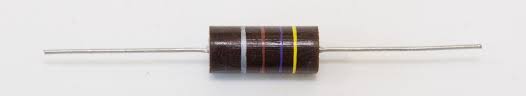
2. 100k ohm resistor (2 watt)
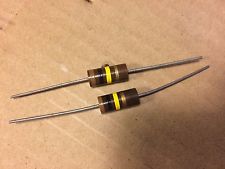
3. 1k ohm resistor (2 watt)
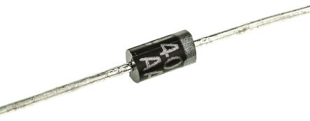
4. 1N4007 diode
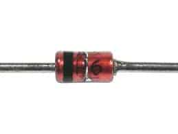
5. One zener diode 5 volts
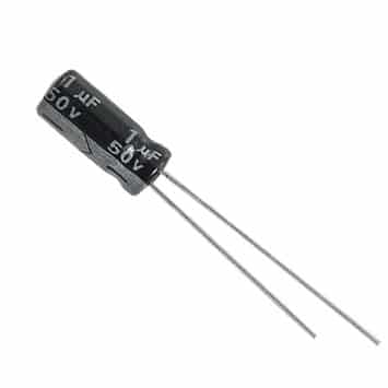
6. 1 uf capacitor
7. Connecting wires
CIRCUIT DIAGRAM:
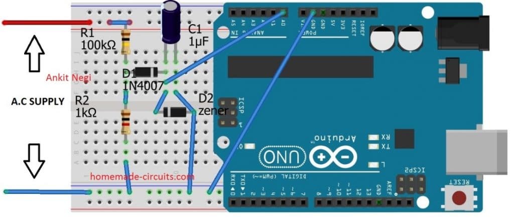
Make connections as shown in circuit diagram.
A) Make a voltage divider using resistors keeping in mind that 1 k ohm resistor should be connected to ground.
B) Connect diode’s p- terminal directly after 1 k ohm resistor as shown in fig. and its n- terminal to 1 uf capacitor.
C) Don’t forget to connect zener diode in parallel to the capacitor( I have explained below)
D) Connect a wire from positive terminal of capacitor to the analog pin A0 of arduino.
E) ** do connect the ground pin of arduino to the overall ground else circuit will not work.
OBJECTIVE OF ARDUINO::
Well you can use any microcontroller, but I have used arduino due to its easy IDE. Basically function of arduino or any microcontroller here is to take voltage across 1 k ohm resistor as analog input and convert that value into mains a.c. voltage value by using a formula (explained in working section). Arduino further print this mains value on serial monitor or laptop screen.
VOLTAGE DIVIDER CIRCUIT:
As already mentioned in component section, resistors (which makes up a voltage divider circuit) must be of high power rating as we are going to connect them directly to mains a.c supply.
And hence this voltage divider circuit replaces the transformer. Since arduino can take maximum of 5v as analog input, voltage divider circuit is used to split mains high voltage into low voltage (less than 5v).Let’s make an assumption that mains supply voltage is 350 volts ( r.m.s )
Which gives maximum or peak voltage = 300*1.414= 494.2 volts
So peak voltage across 1 k ohm resistor is = (494.2volts/101k)*1k = 4.9volts ( maximum )
Note:* but even for 350 r.m.s this 4.9 volts is not r.m.s that means in reality voltage on analog pin of arduino will be less than 4.9 v.
Hence from these calculations it is observed that this circuit can safely measure a.c voltage around 385 r.m.s.
WHY DIODE?
Since arduino cannot take negative voltage as input, it’s very important to remove negative part of input a.c sin wave across 1 k ohm resistor. And to do so it is rectified using a diode. You can also use a bridge rectifier for better results.
WHY CAPACITOR?
Even after rectification there are ripples present in wave and to remove such ripples, a capacitor is being used. Capacitor smooth out the voltage before feeding it to arduino.
WHY ZENER DIODE
Voltage greater than 5 volts can damage arduino. Hence to protect it, a 5 v zener diode is used. If a.c mains voltage increases beyond 380 volts i.e. greater than 5 volts on analog pin, breakdown of zener diode will occur. Thus shorting the capacitor to ground. This ensures safety of arduino.
CODE:
Burn this code in your arduino:
int x;           // Initialize variable x
float y;         // Initialize variable y

void setup() {
  pinMode(A0, INPUT);       // Set pin A0 as input
  Serial.begin(9600);       // Begin serial communication at 9600 baud
}

void loop() {
  x = analogRead(A0);       // Read analog value from pin A0 across capacitor
  y = x * 0.380156;         // Convert analog value into AC supply voltage using formula

  Serial.print("Analog Input: "); // Label for analog value
  Serial.print(x);                // Print analog value

  Serial.print(" | AC Voltage: "); // Label for converted AC voltage
  Serial.print(y);                 // Print AC voltage

  Serial.println();               // Move to next line
  delay(500);                     // Optional: add a small delay to stabilize readings
}
Understanding code:
1. VARIABLE x:
X is the input analog value received (voltage) from pin A0 as specified in the code i.e.,
x = pinMode (A0,INPUT) ; // set pin a0 as input pin
2. VARIABLE Y:
To arrive at this formula y=(x*.380156), first we have to do some sort of calculations:
This circuit here always provides voltage less than the actual value on pin A0 of arduino due to capacitor and diode. Which means voltage on analog pin is always less than the voltage across 1 k ohm resistor.
Hence we have to find out that value of input ac voltage at which we get 5 volts or 1023 analog value on pin A0. By hit and trial method, that value is around 550 volts (peak) as shown in simulation.
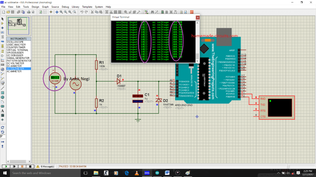
In r.m.s 550 peak volts = 550/1.414= 388.96 volts r.m.s. Hence for this r.m.s value we obtain 5 volts on pin A0. So this circuit can measure maximum of 389 volts.
Now for 1023 analog value on pin A0 --- 389 a.c volts = y
Which gives, for any analog value(x); y = (389/1023)*x a.c volts
OR y =.38015*x a.c volts
You can clearly observe in fig that printed a.c value on serial monitor is also 389 volts
Printing required values on screen::
We require two values to be printed on serial monitor as shown in the simulation picture:
1. Analog input value received by analog pin A0 as specified in the code:
Serial.print(" analaog input ") ; // specify name to the corresponding value to be printed
Serial.print(x) ; // print input analog value on serial monitor
2. Actual value of ac voltage from mains as specified in the code:
Serial.print(" ac voltage ") ; // specify name to the corresponding value to be printed
Serial.print(y) ; // prints the ac value on Serial monitor
WORKING OF THIS TRANSFORMERLESS AC VOLTMETER USING ARDUINO
1. Voltage divider circuit converts or step down the mains ac voltage into corresponding low voltage value.
2. This voltage after rectification is taken by analog pin of arduino and by using formula
y = 0.38015*x a.c volts is converted into actual mains a.c value voltage.
3. This converted value is then printed on serial monitor of arduino IDE.
SIMULATION:
To see how close the printed value on screen to the actual a.c value, simulation is run for different values of a.c voltages :
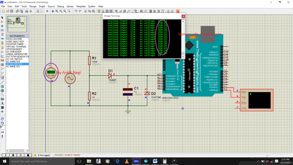
A) 220 volts or 311 amplitude
B) 235 volts or 332.9 amplitude

C) 300 volts or 424.2

Hence from the following results it is observed that for 220 a.c supply, arduino shows 217 volts. And as this a.c value increases, results of simulation become more accurate that is more close to the input a.c value.


Comments
Sir I did this type of circuit, but I added a little function to it. And the function is that when the voltage is above or below certain value the relay switch should be energised, but once the relay energies the LCD give error display,but if the relay is not connected the LCD and the reading is correct. Pls help me out with this problem sir
Hi Oluwadamilare, how did you connect the relay? This type of power supply will not be able to drive a relay directly. Please show me your schematic I’ll try to help
Can you use a 1N4007 diode instead of a zener diode?
zener is placed to create 5V for the Arduino…
Sir, How to measure 3 phase voltage .For 3 phase 3 wire system.
According to me, you can measure the AC voltage across any one of the 3 lines, that will be the voltage reading for all the 3 phase system.
But I have to measure 3 voltages individually to measure unbalanced or not. So can you please tell me how to measure?
measure them across an earthing or ground line. Temporary ground line can be obtained from your bathroom metal pipes and taps
Sir, Is it possible if I short 4.7 k resistors across three phases (star connection) and make use of that as ground point?
yes that can be tried..
it is PROTEUS
can i change the value of resistors of voltage divider circuit??? if yes then what changes i will have to do in prgm or ckt?
you can change, but it must proportionate to the shown ratio (100:1 as per the author), and preferably the 100K value should not be reduced