In this post I will show how to construct wireless office calling bell which can be used for calling 6 different personnel from head’s / boss’s desk or some other calling bell type fun project for your home.
Using nRF24L01 2.4 GHz module
We will be constructing a simple wireless calling bell using Arduino and nRF24L01 2.4 GHz module, which can work around your home or your office without any hiccups or coverage issue.
The proposed circuit can be powered from a 5V smartphone adapter or any inexpensive 5V adapter which keeps your circuit alive and ready to hear your call.
Let’s look an overview of nRF24L01 2.4 GHz module.
Technical Datasheet
The nRF24L01 is a 2.4 GHz transceiver module for wireless communication.
Main Specifications:
Operating Voltage: 1.9V to 3.6V (use 3.3V for Arduino).
Current Consumption:
- Transmit (TX) Mode: 11.3 mA at 0 dBm power.
- Receive (RX) Mode: 12.3 mA.
- Power-Down Mode: 900 nA.
- Data Rate: Up to 2 Mbps.
- Output Power: Configurable from -18 dBm to 0 dBm.
Power Requirements
Voltage: You must use a stable 3.3V supply. A 10 µF capacitor between VCC and GND near the module is recommended to filter voltage spikes.
SPI Communication Timing
The module communicates using SPI with the following connections:
- CE: Connect to Arduino digital pin 9.
- CSN: Connect to Arduino digital pin 10.
- SCK: Connect to Arduino digital pin 13.
- MOSI: Connect to Arduino digital pin 11.
- MISO: Connect to Arduino digital pin 12.
The SPI clock speed can go up to 10 MHz.
Transmission Range Calculation
The range depends on the power, the antenna, and the environment.
Free-Space Range Formula:
Maximum Range ≈ √(Pt × Gt × Gr / ((4 × π × f)² × S))
Where:
- Pt = Transmit power in watts.
- Gt = Transmit antenna gain (default: 1).
- Gr = Receive antenna gain (default: 1).
- f = Frequency in Hz (2.4 GHz = 2.4 × 10⁹ Hz).
- S = Receiver sensitivity in watts (-85 dBm = 3.16 × 10⁻⁹ W).
Example Calculation:
For Pt = 0.001 W, f = 2.4 * 109 Hz, and S = 3.16 * 10-9 W:
Maximum Range ≈ √(0.001 * 1 * 1 / ((4 * π * 2.4 * 109)² * 3.16 * 10-9)).
Simplifying to estimate the range.
Data Rate and Power Consumption
In case you are using higher data rates (e.g. 2 Mbps) then it will consume more power but reduce communication time. Lower transmit power levels (-6 dBm, -12 dBm, -18 dBm) save energy but reduce range.
Current Consumption Calculation
Transmit Power Consumption:
Power = Voltage × Current
For TX at 0 dBm, Current = 11.3 mA = 0.0113 A
Power = 3.3 × 0.0113 = 0.03729 W
Receive Power Consumption:
For RX, Current = 12.3 mA = 0.0123 A
Power = 3.3 × 0.0123 = 0.04059 W
Interference and Channel Selection
The module operates on the 2.4 GHz band, shared with Wi-Fi and Bluetooth.
You can Use non-overlapping channels (e.g. 1 to 125) to minimize interference.
Packet Handling
The module supports:
Payload Size: 1 to 32 bytes.
Address Width: 3 to 5 bytes for unique device identification.
CRC Check: 1 or 2 bytes for error detection.

Detailed Description
The above chip is called nRF24L01 module. It is a duplex (bi-directional) communication circuit board designed for microcontrollers and single board computers like Raspberry Pi.
It utilizes 2.4 GHz frequency which is ISM band (Industrial, Scientific and Medical band) it is the same frequency used in Wi-Fi communication.
It can transmit or receive data at the rate of 2Mbps, but in this project the transmission and reception is limited to 250 Kbps because of lower data requirements and lowering the data rate will results in increased overall range.
It consumes only 12.3 mA at peak data transmission which makes battery friendly device. It utilizes SPI protocol for communicating with microcontroller.
It has transmission / reception range of 100 meter with no obstacle in between and about 30 meter range with some obstacle.
You can find this module on popular e-commerce sites, also at your local electronics store.
Note: The module can work from 1.9 to 3.6V, the on board regulator on the Arduino can provide 3.3V for the module. If you connect the nRF24L01’s Vcc terminal to 5V of Arduino’s output, this will result in malfunction of the module. So care must be taken.
That’s the brief introduction to the nRF24L01 module.
Let’s investigate the details of the circuit diagram:
The Remote Control Circuit:
Remote will be with the boss or the head of the office.
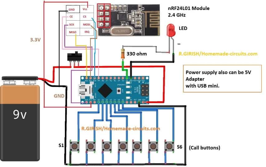
The remote consists of Arduino nano; by the way you can use any Arduino board, 6 push buttons for ringing six different receivers, nRF24L01 module and a LED for acknowledging the push of a button.
You can power this using 9V battery or from 5V adapter. In case of battery you should turn off this remote after your call.
Now let’s look at the code. Before that you need to download the library file only then the code gets compiled.
Link: github.com/nRF24/RF24.git
Code for Remote:
// --------- Program Developed by R.GIRISH / homemade-circuits.com ---------//
// Simple RF transmitter code using nRF24L01
// Sends the same text message to different receiver addresses
// based on which input pin is triggered
// ------------------------------------------------------------------------//

#include <SPI.h>          // SPI library for nRF24L01 communication
#include <RF24.h>         // RF24 library

// CE pin = 9, CSN pin = 10
RF24 radio(9, 10);

// Unique RF addresses for six different receivers
const byte address_1[6] = "00001";
const byte address_2[6] = "00002";
const byte address_3[6] = "00003";
const byte address_4[6] = "00004";
const byte address_5[6] = "00005";
const byte address_6[6] = "00006";

// Input pins (push buttons or trigger inputs)
const int input_1 = A0;
const int input_2 = A1;
const int input_3 = A2;
const int input_4 = A3;
const int input_5 = A4;
const int input_6 = A5;

// Status LED pin
const int LED = 2;

// Data to be transmitted
const char text[] = "call";

void setup()
{
  // Configure input pins
  pinMode(input_1, INPUT);
  pinMode(input_2, INPUT);
  pinMode(input_3, INPUT);
  pinMode(input_4, INPUT);
  pinMode(input_5, INPUT);
  pinMode(input_6, INPUT);

  // Enable internal pull-up resistors
  // Inputs will read LOW when button is pressed
  digitalWrite(input_1, HIGH);
  digitalWrite(input_2, HIGH);
  digitalWrite(input_3, HIGH);
  digitalWrite(input_4, HIGH);
  digitalWrite(input_5, HIGH);
  digitalWrite(input_6, HIGH);

  // LED output
  pinMode(LED, OUTPUT);
  digitalWrite(LED, LOW);

  // Initialize RF module
  radio.begin();
  radio.setChannel(100);               // RF channel (must match receiver)
  radio.setDataRate(RF24_250KBPS);     // Low data rate for better range
  radio.setPALevel(RF24_PA_MAX);       // Maximum transmit power
  radio.stopListening();               // Set module as transmitter
}

void loop()
{
  // If input_1 is triggered
  if (digitalRead(input_1) == LOW)
  {
    radio.openWritingPipe(address_1);
    radio.write(&text, sizeof(text));
    digitalWrite(LED, HIGH);
    delay(400);
    digitalWrite(LED, LOW);
  }

  // If input_2 is triggered
  if (digitalRead(input_2) == LOW)
  {
    radio.openWritingPipe(address_2);
    radio.write(&text, sizeof(text));
    digitalWrite(LED, HIGH);
    delay(400);
    digitalWrite(LED, LOW);
  }

  // If input_3 is triggered
  if (digitalRead(input_3) == LOW)
  {
    radio.openWritingPipe(address_3);
    radio.write(&text, sizeof(text));
    digitalWrite(LED, HIGH);
    delay(400);
    digitalWrite(LED, LOW);
  }

  // If input_4 is triggered
  if (digitalRead(input_4) == LOW)
  {
    radio.openWritingPipe(address_4);
    radio.write(&text, sizeof(text));
    digitalWrite(LED, HIGH);
    delay(400);
    digitalWrite(LED, LOW);
  }

  // If input_5 is triggered
  if (digitalRead(input_5) == LOW)
  {
    radio.openWritingPipe(address_5);
    radio.write(&text, sizeof(text));
    digitalWrite(LED, HIGH);
    delay(400);
    digitalWrite(LED, LOW);
  }

  // If input_6 is triggered
  if (digitalRead(input_6) == LOW)
  {
    radio.openWritingPipe(address_6);
    radio.write(&text, sizeof(text));
    digitalWrite(LED, HIGH);
    delay(400);
    digitalWrite(LED, LOW);
  }
}

// --------- Program Developed by R.GIRISH / homemade-circuits.com ---------//
That concludes the remote / transmitter.
Now let’s look at the receiver.
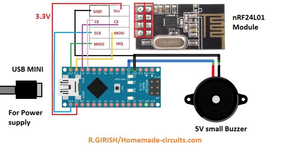
The Receiver Circuit:
NOTE: You can make one receiver or six receivers depending on your needs.
The receiver consists of Arduino board, nRF24L01 module and a buzzer. Unlike the remote, receiver should be powered from 5V adapter, so that you don’t depend on the batteries which will drain within couple of days.
Now let’s look at the code for receiver:
Program Code for the Receiver
// --------- Program Developed by R. GIRISH / homemade-circuits.com ---------
// Purpose: NRF24L01 receiver that activates a buzzer when data is received
// -------------------------------------------------------------------------

#include <SPI.h>          // SPI library required for NRF24L01 communication
#include <RF24.h>         // NRF24L01 library

// CE pin = 9, CSN pin = 10 (matches the existing circuit)
RF24 radio(9, 10);

// Buzzer connected to digital pin 2
const int buzzer = 2;

// Buffer to store received data (max payload size for NRF24L01 is 32 bytes)
char text[32] = "";

// -------- Change this address only if transmitter address is changed --------
const byte address[6] = "00001";
// ---------------------------------------------------------------------------

void setup()
{
  // Initialize serial monitor for debugging (optional)
  Serial.begin(9600);

  // Set buzzer pin as output
  pinMode(buzzer, OUTPUT);
  digitalWrite(buzzer, LOW);   // Ensure buzzer is OFF at startup

  // Initialize NRF24L01 module
  radio.begin();

  // Set receiver address (must match transmitter)
  radio.openReadingPipe(0, address);

  // Set RF channel (0–125). Higher channel reduces WiFi interference
  radio.setChannel(100);

  // Set data rate to 250 kbps for better range and stability
  radio.setDataRate(RF24_250KBPS);

  // Set maximum power amplifier level
  radio.setPALevel(RF24_PA_MAX);

  // Put NRF24L01 in listening (RX) mode
  radio.startListening();
}

void loop()
{
  // Check if any data is available from transmitter
  if (radio.available())
  {
    // Read the received data into buffer
    radio.read(&text, sizeof(text));

    // Optional: print received data for debugging
    Serial.print("Received: ");
    Serial.println(text);

    // Activate buzzer to indicate successful reception
    digitalWrite(buzzer, HIGH);
    delay(1000);               // Buzzer ON time (1 second)
    digitalWrite(buzzer, LOW);
  }
}

// --------- Program Developed by R. GIRISH / homemade-circuits.com ---------
NOTE:
If you are going to build more than one receiver for this office call bell system, then you should change the mentioned value on successive receiver build and upload the code.
For the first receiver (no need to change anything):
// ------- Change this ------- //
const byte address[6] = "00001"; and upload the code.
// ------------- ------------ //
For the second receiver (You have to change):
const byte address[6] = "00002"; and upload the code.
For the third receiver (You have to change):
const byte address[6] = "00003"; and upload the code.
And so on…….. up to “00006” or the sixth receiver.
When you press “S1” on the remote, the receiver with address “00001” will respond / buzz.
When you press “S2” on the remote, the receiver with address “00002” will respond / buzz.
And so on……
That concludes the receiver circuit details.
One more important hardware tip (very common issue)
If compilation succeeds but radio doesn’t work, then please make sure to add:
- 10µF.....47µF capacitor across VCC and GND of NRF24L01
(This is critical step, ....many people miss it.)
If you have more questions, please feel free to express them in the comment section, we will try to get back to you soon with a reply


Questions & Answers
hi sir, hope all is going well…sir i read this article and try to understad. i have some questions, if i used this module for door bell and another for control the appliances with relay. like 2 projects with nrf24 module at same place. both are seperate interface or module can conflict?
if internet notworking due to some issues, communication also disconnected or wa can use?
for operating relays is there any way to operate manual if its disconnected due to internet?
Thank you Ghulam,
Yes you can use two separate NRF24L01 projects at the same location and they will not conflict. However, each project must use a different RF address or channel. If the address and channel are different, then both systems work independently and therefore they do not interfere with each other.
NRF24L01 does not use the internet in any way. It works purely on local 2.4 GHz wireless communication, so even if the internet is completely down, then also communication between the transmitter and receiver will still continue to work normally, no issue there.
For relay control, manual operation is always possible. You can therefore, add simple push buttons or switches directly to the Arduino inputs and then turn the relay ON or OFF locally. So even if wireless communication is not available, control is still possible without depending on anything else.
sir plz guide me about channels, like you used in code radio.setChannel(100). this same we have to used in same reciver code; for another project which range is best. like less than 100 or between 100 to 125? where we can get good range plz? RF address; also guide me plz
Hi Ghulam, Yes, same channel must be used in both transmitter and receiver, otherwise they will not communicate.
NRF24L01 supports channels 0–125, however range does not depend on higher channel numbers. For better stability therefore avoid Wi-Fi crowded zones.
So recommended is to use channels 90–110….. channel 100 is a safe choice, works fine in most cases.
If multiple projects are running at same place, then use different channels or different RF addresses. But transmitter and receiver of the same project must use exactly the same RF address, otherwise again no link.
Hello Garish,
I have a question.
Can you help me with designing an Arduino controlled LC resonant tank circuit automatic frequency “sense and maintain” circuit.
Essentially I need to be able to first determine the LC tanks’ natural resonant frequency before powering up the entire circuit.
LC sensing contacts of some sort would first “ping” the LC components, causing the natural resonant frequency to be generated. This frequency could be connected to the input to the Arduino, which would generate the proper variable output signal for a 10 k ohm, 8pdip digital potentiometer. The digital pot’s resistive output would supply the control to the tank’s input clock circuitry. Presently that is accomplished with a Bourne 10 k /10 turn, wire-wound pot.
The system, minus the pot, would be powered at 12 VDC, with the pot being powered at 5 VDC. The system will need circuitry to boost the pot’s output back up to 12 VDC.
Can and will you help?
Thank you in advance for anything you can help me with this task.
Hi Scott,
here’s the email ID of Mr. GR, you can contact him directly:
girishisro7
@
gmail.com
Hi Gerald,
Please check does this project suit your requirements: https://www.homemade-circuits.com/24-ghz-10-channel-remote-control-switch/
Regards
Good day sir, I am Gerald Aka aka from Nigeria. My question is, what changes can I make to make A single receiver to respond to all the addresses and light up six (6) LEDs depending on the address received? Am asking because I will like the device as a switch my house… Thanks for your response.