In this post, I will show how to construct a DC voltmeter using Arduino where the readings are displayed in 16x2 LCD.
The proposed voltmeter design can read up to 30V with tolerance of +/- 0.5 volt. We are going to see how this setup functions and explore other possibilities we can accomplish other than measuring voltage.
This project is fairly simple, even beginners can accomplish with ease, but care must be taken while prototyping the circuit as we are going to apply external voltage, any misconnection to Arduino can lead to fatal damage to your board.
Let the warning be a side, let’s explore how it functions.
Here, we are using analogue to digital conversion process. Voltage from any source is analogue function; the readings displayed on 16x2 LCD is a digital function.
The challenge is converting those analogue functions to digital function. Fortunately, Arduino has functionality to read analogue functions and convert them to discrete function.
Arduino microcontroller equipped with 10-bit analogue to digital converter (ADC). This means Arduino can read 2^10=1024 discrete voltage levels.
In other words, the voltage applied to analogue pin of Arduino is sampled 1024 discrete voltage levels with respect to a reference voltage; the sampled value gets displayed in the LCD. This is the principle behind this voltmeter or almost any digital voltmeter.
However, the applied external voltage is not directly measured by Arduino. The voltage is step down with help of voltage dividers and some math is done in the program in order to get actual voltage reading.
How it Works
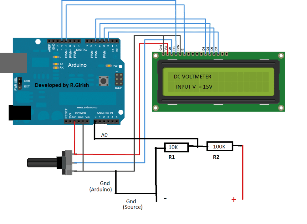
The circuit consists of two resistors, one LCD display and an Arduino which is brain of the digital voltmeter. The two resistor acts as voltage divider, the node of the divider is connected to analogue pin # A0 of the Arduino, which reads the input voltage. Ground connection is established between Arduino and external voltage source.
The minimum voltage which can measure by this voltmeter is 0.1V, this threshold is set in the program, so that it reads 0.00 volt after disconnecting the voltage source and does not display readings due to static charge around the measuring probe.
Author’s prototype:
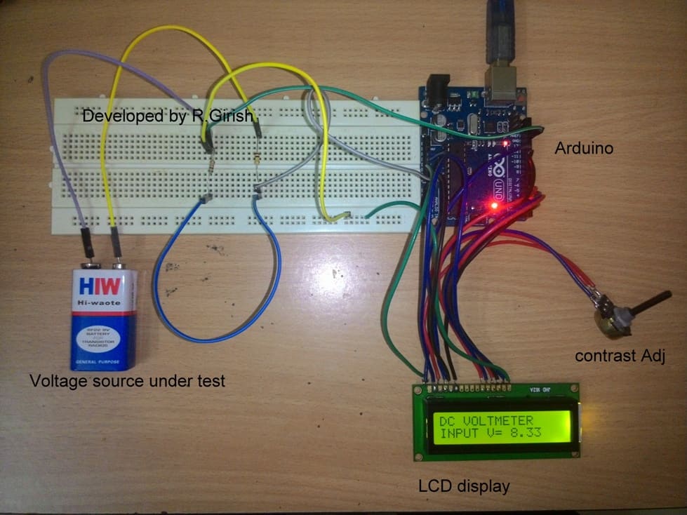
Don’t reverse the polarity while measuring the voltage, it won’t harm the circuit but, it does not read any voltage and displays 0.00 V, until you correct the polarity. Adjust the contrast of LCD display to optimum level by rotating the potentiometer.
Make sure you don’t apply any voltage source which could spike higher than 30V; it may damage your Arduino board. Technically you can bump up the maximum measuring voltage of this circuit by changing resistor values and modifying the program, but for the illustrated setup 30V is limit.
For accurate reading, choose fixed resistors with minimum tolerance value, resistors play an important role in calibrating the voltage reading.
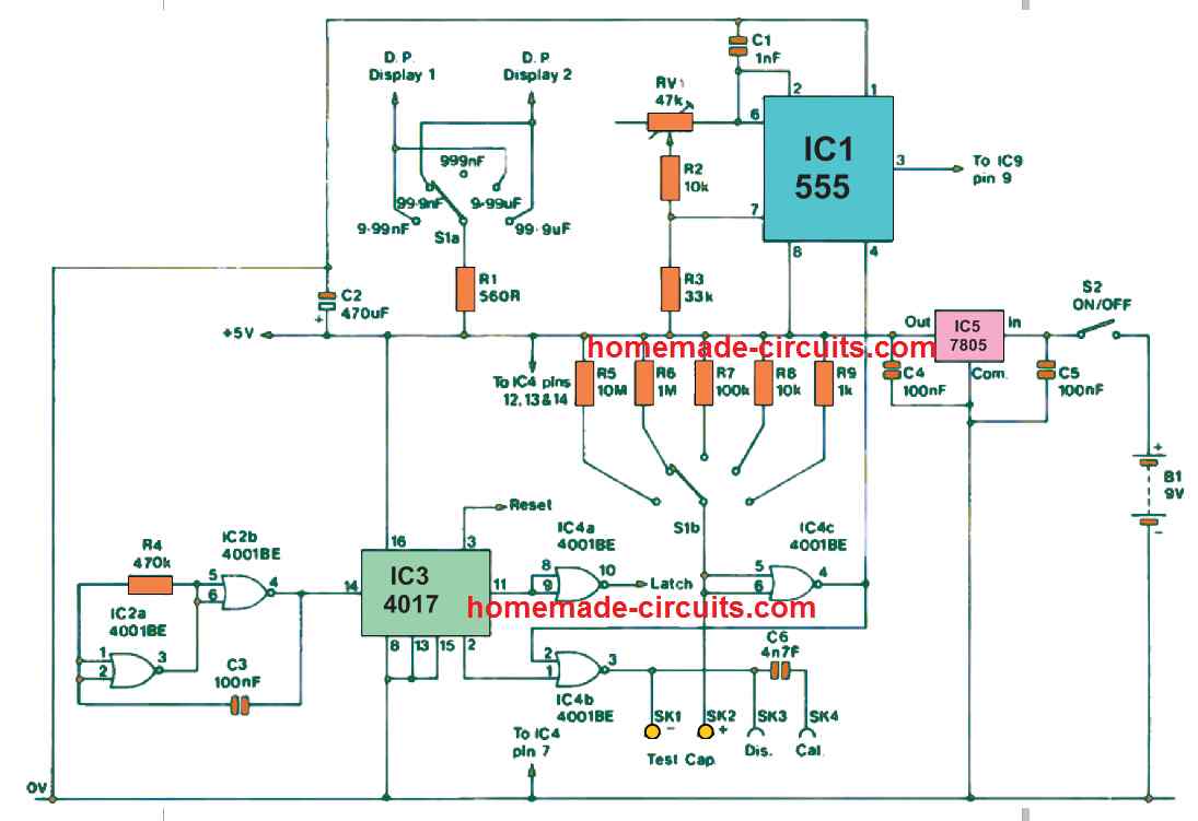
Circuit diagram:
The other possibility of this voltmeter is that we can modify the program to automate some tasks.
For instance, detect full battery voltage and disconnect the battery from its charger or disconnect battery if voltage goes below preset voltage level and so on, these task can be accomplished even without LCD display. However this is subject of another article.
Program:
//--------Program developed by R.Girish (Optimized)---------//
#include <LiquidCrystal.h>

LiquidCrystal lcd(12, 11, 5, 4, 3, 2);

const int analogInput = A0; // Clearly defining it as an Analog pin
float vout = 0.0;
float vin = 0.0;
float R1 = 100000.0; // 100k Resistor
float R2 = 10000.0;  // 10k Resistor
int value = 0;

void setup()
{
  pinMode(analogInput, INPUT);
  lcd.begin(16, 2);
  lcd.print("DC VOLTMETER");
}

void loop()
{
  value = analogRead(analogInput);

  // Using 1023.0 for exact max ADC step
  vout = (value * 5.0) / 1023.0;
  vin = vout / (R2 / (R1 + R2));

  if (vin < 0.10) {
    vin = 0.0;
  }

  // Update only the second row
  lcd.setCursor(0, 1);
  lcd.print("INPUT V= ");
  lcd.print(vin);
  lcd.print("V  "); // Extra spaces clear out old characters if the number shrinks

  delay(500);
}
//--------Program developed by R.Girish---------//
Please check the readings with a good voltmeter/multimeter.
Important:
Since you are using a 100k ohm (R1) and 10k ohm (R2) voltage divider, so please keep the following in mind:
First the maximum voltage you can measure is 55V. Do not supply more than 55V into this circuit, or the voltage hitting the Arduino pin will exceed 5V and cause permanently damage to the board.
Second you must connect the ground (GND) of the external voltage source you are measuring to the Arduino's GND pin. Without a shared ground reference, your readings will be completely erratic and inaccurate.
Questions & Answers
Dear Swagatham,
As usual, a very useful circuit idea.
I want to setup this to read 4*12v lead acid battery (actual voltage could be about 60v). What should be the resistor values and what needs to changed in the program ?
in a real setup I need the voltage to be transmitted using bluetooth from the 2nd floor to ground floor and displayed.
once again thank you very much for presenting this idea.
Thank you Dear Suresh,
I understand that you want to read 60 V using this Arduino circuit, however, as you can see the maximum limit of this circuit is only 30 V, therefore it may not be possible to use 60 V with this circuit set up.
Dear Swagatham,
Thanks for the reply. I intend to work on this idea.
No problem Suresh, I appreciate your interest.
All the best to you!
hello! is there any way to build a current indicator with LEDs like vu meter , somthing with OP-amps , and indicat the current with LEDs , like 0.1A, 0.2A,,, 0.5A, 1A, 1.5A , 2A , 2.5 ……..10A
That’s easily possible using the IC LM3915. Just add a current sensing resistor across its pin5 and ground, as the potential difference across the resistor rises, it will be reflected through the 10 LEDs connected across the ICs output pins.
thank you 🙂
hi swagatam,
i am working on a industrial product of battery voltage data logger.
I have designed some circuits for that. but i have doubts in that circuit so could you please help me regrading this project.
if you could just send me your mail id then i can tell you the concept and work done by me.
my mail id is nikhil.kakade123@gmail.com
Hi Nikhil, I can surely look into it and try my best to help you out, but I would be willing to do that only if I am allowed to share it in this website later on, I hope you won't mind it.
My email is hitman2008
@ live.in
hi swagatham,