
In this post I am going to explain different types of electrical transformers that are used in a wide variety of applications. Transformers can be classified in many different ways, for example: based on their input / output character, voltage, frequency, application, power handling capacity etc. In this post we will be exploring all the […]
Explained
FET Current Source: Explained with Formulas

An FET Current Source is one special type of active circuit that is using a Field Effect Transistor for giving a steady and constant current into a circuit. We are doing this because sometimes we want that current should not change, it should remain fixed and stable. Why We Need Constant Current Now you may […]
DPDT Relay Working, Pinouts, Testing Explained

In this post we are going to understand about how this DPDT relay actually works, how we identify its pinouts, and how we can use it in our projects. We shall go step by step so that you can feel confident with every small thing about it. Introduction We know that a DPDT relay means […]
Constant Current Generator Circuits Explained
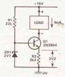
Constant current generators (CCGs), as the name suggests, are circuits designed to produce a steady load current regardless of significant fluctuations in load resistance or voltage levels. Basic Constant Current Generator Circuit Illustrated in Figure 1 is a basic example of such a circuit. In this configuration, Q1 operates in the common emitter mode. A […]
How to Select MOV – Explained with a Practical Design
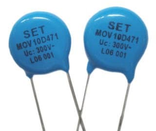
MOVs or metal oxide varistors are devices designed for controlling mains switch ON surges in electrical and electronic circuits. Selecting an MOV for a particular electronic circuit might require some consideration and calculation, I have explained the procedures here. What are MOVs Metal oxide varistors or simply varistors are non-linear surge suppressor devices which are […]
Inductors in AC/DC Circuits Explained
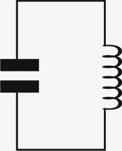
In this post I have explained the response of inductors to DC and AC voltages as well as when applied with capacitors which is often used as a complementing part with an inductor. Properties of Inductor Inductors are known for their property of storing electrical energy in them in the form of magnetic energy. This […]