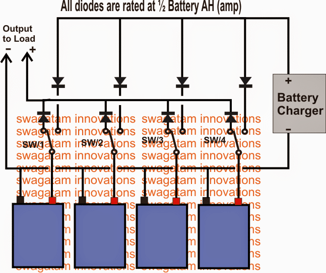
In this post I have explained two methods of connecting batteries in parallel. The first one below deals with changeover circuit using SPDT switches to charge multiple batteries individually or collectively. These may be connected in parallel using a single battery charger and through a manual SPDT changeover switch bank. The seconds design talks about […]
Explained
Accumulators Explained [Rechargeable Batteries]
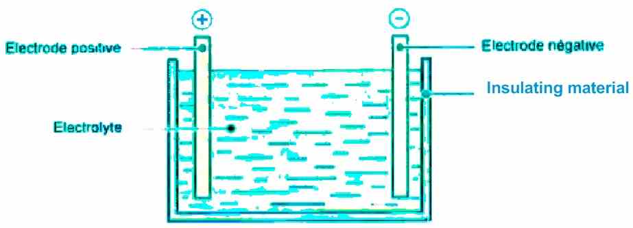
Unlike dry batteries, whose stored electrical energy can only be used once, accumulators have the immense advantage of reversibility, which translates into the possibility of a series of charge/discharge cycles. This means that they can undergo a series of charge/discharge cycles. They are found in applications that may require more power, such as starting the […]
Types of Batteries Explained [NiCd, NiMH, Lead Acid, Li-Ion]
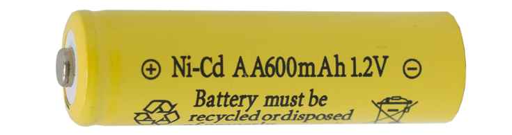
In this post I have explained the main types of batteries that are widely used in today’s world for almost all important applications, ranging from cars, automobiles mobile phones, airplanes, industries, satellites to name a few. The Nickel Cadmium (NiCd) Battery Fundamentally, the NiCd battery adopts fast charging as opposed to slow charging and employs […]
Vehicle Immobilizer Circuit Explained
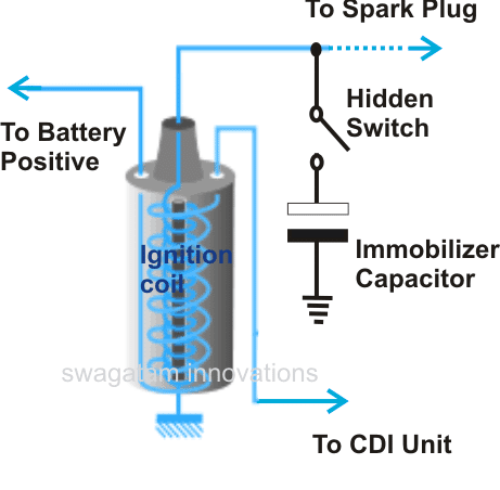
If you own a car and still haven’t incorporated any security system in it or perhaps your old security system is out of order, you can quickly opt for a cheap yet effective security option for your car or any vehicle by installing the proposed circuit. It will cost you not more than a dollar. […]
Simplest Piezo Driver Circuit Explained
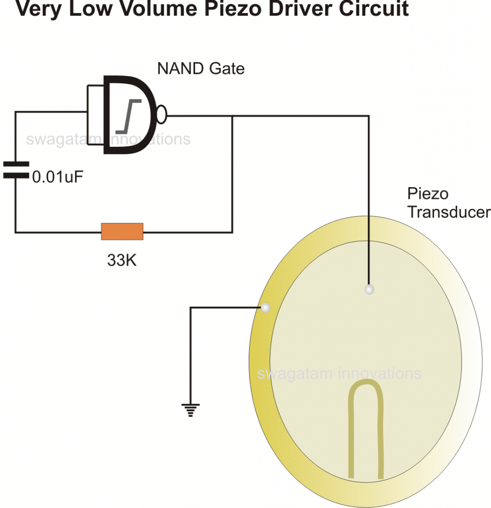
In the previous post I explained a piezo transducer element and learned how to use it with electronic circuits. In this article we will see how a piezo tranducer can be driven or operated using a simple circuit. As discussed earlier a piezo transducer basically requires a frequency to vibrate and reproduce the required sound. […]
6 Simple Class A Amplifier Circuits Explained
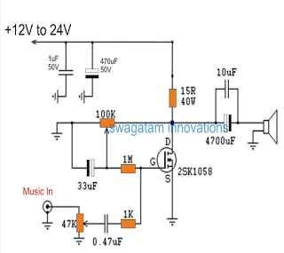
In this post I have explained 6 simple, cheap class A power amplifier circuits which can be used for any small scale audio amplifier application. By: Dhrubajyoti Biswas 1) Zero Negative Feedback Amplifier This following data will detail how to build an amplifier having zero negative feedback which implies building a zero component amplifier. The […]