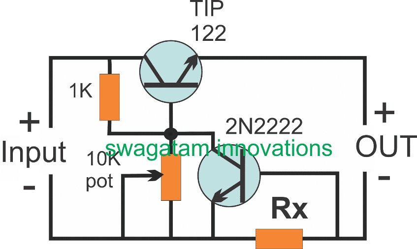
In this post I will try to analyze what is constant current source and how it affects a load, or how it may be used with a load correctly for achieving the most efficient results. The following discussion between me and Mr. Girish will clearly explain what is CC or how constant current operates. How […]
Explained
Elementary Electronics Explained
For a beginner in electronics, constructing basic electronic projects from a circuit diagram could be overwhelming. This quick guide is intended to assist newbies by enabling them handy details about electronic parts as well as regarding techniques of building circuits. We will examine elementary parts like resistors, capacitors, inductors, transformers and potentiometers. RESISTORS A resistor […]
6 Simple AC Bridge Circuits Explained
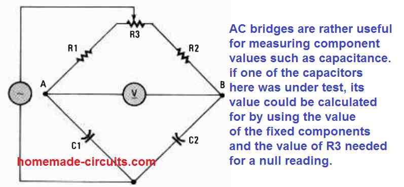
An AC bridge is a circuit which can be used for measuring parameters like capacitance, resistance, Inductance using differential method, by comparing them with known values of similar components, positioned diagonally across a bridge circuit, and through an analogue meter placed at the center of the bridge. Before we begin talking about the AC bridge […]
Simple Triac Triggering Circuits Explained
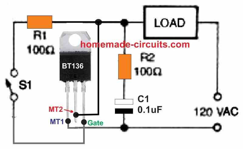
In this post I have explained the fundamental methods of triggering a triac, and also discuss the right way to connect the terminals of a triac. Triacs are solid-state bidirectional thyristors that can switch across both the AC half cycles on a 120-volt or 240-volt Ac power system. A triac could be activated (switched on and […]
Communication Protocols in Microcontrollers Explained
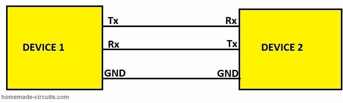
In this post I am going to explain various communication protocols that are used by microcontrollers, microprocessors and ICs for communicating with various sensors, electronic drivers, input and output devices. We will see: Why do communication protocols exist in electronics? UART protocol. I2C or IIC or “I squared C” protocol. SPI or Serial Peripheral Interface […]
Clipper and Clamper Circuits Explained
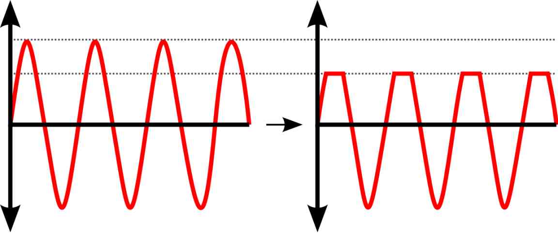
In this post I am going to explain clipper and clamper circuits. The clipper and clamper are called wave shaping circuits because they convert the incoming signal wave to another kind of useful wave. They are used widely in power supplies, filter circuits, RF transmitters / receivers, voltage suppressors, audio amplifiers and the list goes […]