In this post I have explained a LED music power level indicator for indicating a subwoofer bass power range, which can be also modified as an effective dancing Electroluminescent Wire light show. The idea was requested by Mr. David.
Technical Specifications
Here's an idea or suggestion for your projects or what ever lol
My son picked up some wire that's about 15 in length with simple power and ground connects.
When powered this wire lights up whatever color - his is green. Used for accent or trim around stuff. It's not very bright.
I've been looking at some cold cathodes. Not very familiar with these or the price range.
I've been toying with leds and clear plastic tubing 3/8" od filled with water but can't get the brightness or any distance. Any ideas or suggestion.
Kinda shooting for the lights around the top of a sonic drive-in but of coarse not that bright. Also need something to pick up sound to blink with the bass beat.
And lastly - which I think is impossible but colby my son says he would praise you as the led God and sing songs of your greatness lol he would like to see the lights blink with music but the louder the music the more distance it would light up.
Example - think of the old eq booster long time ago and the lights would blink with music generally a row right and one left or both going up.
Colby wants to wrap his truck with invention I'm suggesting so it will light up and go around the truck or even around a subwoofer for display. Again thanks for your time. Any questions about our original text or need more pics just lemme know.
Thanks so much David
What's EL Wire or Electroluminescent Wire
The "wire light" as referred in the above request, is actually an EL Wire or Electroluminescent Wire which are nowadays quite popular due to their dazzling light effect, hassle-free connections, and super flexible nature.
These are also popularly known as glow sticks, neon LEd light, EL glowwire, loopstick, neonstring etc.
In the market you might find these devices available in various shapes and sizes such as in the form or wires, tubes, strips, plates and sheets.
Basically these are made by sandwiching phosphor element between two conducting plates, and when these plates are energized with a pulsating DC or an AC, the phosphor electrons between the plates get agitated and in the process start emitting energy in the form of fluorescent illumination.
Different colors are achieved by simply putting a layer of relevant colored vinyl coating over the particular EL device, which cover most primary as well as the secondary colors, thus making the device extremely suitable for decorative purposes.
Electroluminescent sheets are nowadays extensively used in advertisement boards as an effective backlighting, and it serves better than the LEDs due to their enhanced uniformity in terms of light distribution across the panel.
EL devices do not work with DC, simply because phosphor require an oscillating current to become agitated, therefore either an AC or a pulsating DC becomes necessary to make these devices emit light.
Also as the potential difference or the voltage is increased the illumination is also seen to be increasing proportionately, therefore special boost inverters are used for illuminating EL lights for acquiring an optimal brightness from it.
The Design
As per the request a music power level meter circuit can be built by using the versatile IC LM3915, as shown below:
The following first design uses LEDs for the indication purpose:
Circuit Diagram
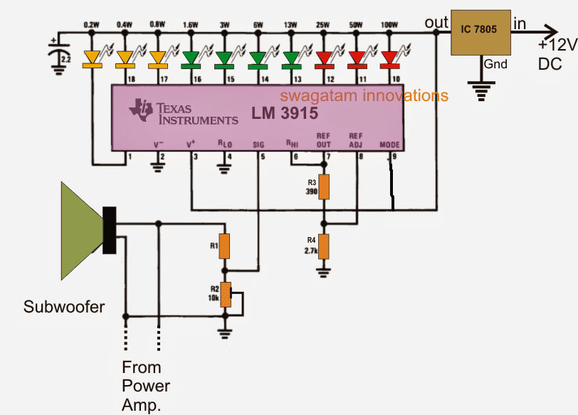
The value of R1 will depend on the speaker impedance rating, for 8 ohms it will be 18k, for 4 ohms it should be 10k, and for 16 ohms it may be increased to 30k approximately.
The IC is LED bar/dot mode sequential driver device, in which the connected LEDs illuminate or "run" back-forth sequentially across the shown array (yellow to red), in response to a rising/falling voltage across its pin#5.
As can be seen in the diagram, the pin#5 is linked with the subwoofer speaker terminal via a voltage divider network R1 and R2.
R2 is in the form of a preset which is adjusted to set the full 10 LED range illumination for a given maximum magnitude of input signal at the pin#5 of the IC.
The above design can also be effectively substituted for illuminating EL wire lights, by implementing a few modification in the circuit.
Connecting the Electroluminescent Wires
In order to include Electroluminescent Wires, the LEDs needs to be replaced with 10 transistor and SCR drivers as shown below:
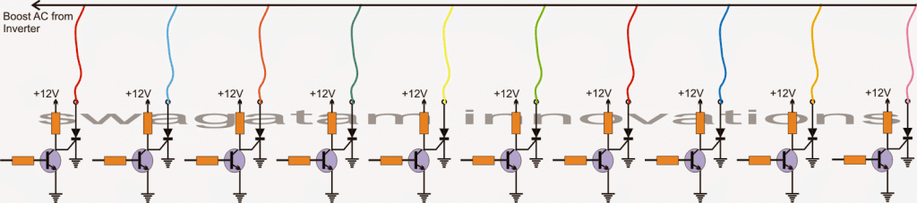
In the above diagram the transistors bases needs to be hooked up with the IC output pinouts from pin#1, and pin#10 to pin#18.
The common top connection of the Electroluminescent Wires can be seen connected with a boost AC supply derived from a boost inverter.
This boost converter can be quite easily made by assembling any standard boost converter circuit, such as a IC 555 boost circuit. I'll be discussing this elaborately soon in one of my future articles in this blog.
In the above shown driver circuit, the transistor bases are fed with a sequentially fluctuating negative signals from the IC in response to the subwoofer bass beats pulses, which switch off the transistors at the same pattern, forcing the SCRs to turn ON with the same effect. This in turn produces a sequentially "running" push-pull show across the entire Electroluminescent Wire string,
220V AC Music Lamp Circuit
The above LM3915 circuit can be easily upgraded into a 220V AC music lamp or 220V dancing music lamp circuits for sequencing 10nos of 100 watt lamps or any other appropriately 220V bulb in response to the input music.
We just have to make 10 nos of the below shown triac stages and integrate them with the 10 outputs of the LM3915 circuit.
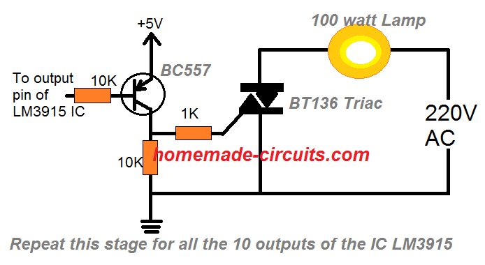
Once done, the indicated AC lamps would start sequencing up and down in a dancing mode in response to the fed input music creating a dazzling DJ music lamp effect.
WARNING: THE ABOVE CONCEPT IS NOT ISOLATED FROM MAINS AC, THEREFORE MAY BE LETHAL TO TOUCH IN OPEN AND POWERED CONDITION. EXERCISE EXTREME CAUTION WHILE TESTING AND HANDLING THIS UNIT.


Comments
Hi
I have a burning question, but since its not related to the topic, can you please tell me where can I ask it
it concerns the output of the lm3915 ic
Thanks
Donald
Hi, you can ask it here:
https://www.homemade-circuits.com/lm3915-ic-datasheet-pinout-application-circuits/
Reply #2
You have some fun Electronic projects that I would like my students build and the Subwoofer Music Level Indicator
is a project that I Am working on now and witing for the IC to come in and I notice tin incorrect pinout in the circuit.
If you have other circuits I can use in my class please send them my way and you will get the credit.
Thank You.
The pinout on the Lm7805 is incorrect, the pinout is 1 in, 2 com, 3 out, your circuit shows differently.
I Am a Professor and I teach Electronics at my University and at our local School Districts when needed.
Hi, Thank you for showing interest in this article, however the IC 7805 is drawn to represent the schematic view of the IC, it is not drawn to show its actual pinouts rather only its positioning details.
I hope the readers will also understand this fact and proceed accordingly.
If you have anymore doubts kindly feel free to discuss.
helo swagatam i wanted to add that circuit to my music system circuit (woofer) but the supply to this system is 15v transformer supply , can that circuit work on 15v if not help me to solve this and be able to integrate it to my system
Hi Davis, yes the above circuit can easily work with a 15V supply…so you can use it with your intended music system.
What is the value of R1
I have updated the info just below the first diagram.