• Skip to main content
  • Skip to primary sidebar

Homemade Circuit Projects

Need circuit help? Post them in the comments! I've answered over 50,000!

Blog | Categories | About | Contact | Calculators-online
You are here: Home / Inverter Circuits / How to Interface Arduino PWM with any Inverter

How to Interface Arduino PWM with any Inverter

Last Updated on August 3, 2020 by Swagatam 4 Comments

In this post I have explained how to interface an existing Arduino PWM signal with any inverter to convert it into a sine wave equivalent inverter. The idea was requested by Mr. Raju Visshwanath

Technical Specifications

I am in need of following inverter circuit designs:

Single phase DC to AC inverter. Input 230 VDC. PWM signals will be sent from Arduino Uno.

Three phase DC to AC inverter. Input 230 VDC. PWM signals will be sent from Arduino Uno.

Can you please let me know your estimated service charges, lead time and payment terms?

Thank you,
Raju Visshwanath

 UPDATE:

Please also refer to this article which explains how to build a simple pure sine wave inverter circuit using Arduino using SPWM......Full Program code also included....

The Design

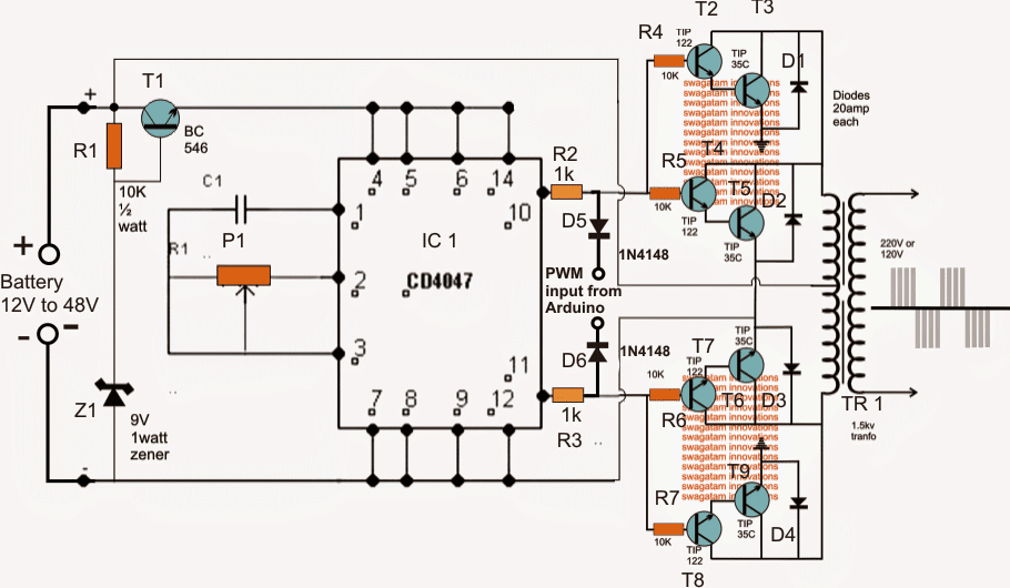
As per the request the first diagram below shows a single phase PWM sine wave inverter using an Arduino feed for the PWMs.

The design looks pretty simple, the 4047 IC is configured as a totem pole astable for generating the basic 50 Hz or 60 Hz frequency.

This frequency drives the two power BJ transistor stages alternately at the specified frequency rate.

The transistors could be replaced with IGBTs for getting better efficiency, but mosfets should be avoided as these may require special attention while designing the PCB, and additional buffer BJT stages to prevent heating up of the mosfets from possible hidden stray inductance or harmonics.

arduino2Binverter2Bcircuit

Circuit Operation

In the above diagram P1 and C1 determine the frequency of the astable which can be adjusted by suitably setting up P1 using a frequency meter for the intended inverter operating frequency.

T1 and the associated components which stabilize a fixed 9V for the IC 4047 may be eliminated if the selected inverter operating voltage is not over 15V, however higher voltage up to 60V could be tried and is recommended for achieving a compact and a more powerful inverter design.

The PWM from the Arduino is applied across voltage divider networks over the two outputs of the IC via reverse biased diodes which make sure that only the negative pulses of the PWMs interact with the power stages and chop their conduction appropriately.
As a result of these PWM chopping effect, the induced current inside the transformer is also correspondingly shaped for achieving the intended PWM sinewave stepped up mains voltage at the secondary of the transformer.

The PWM frequency from the Arduino must be set at around 200 Hz, if a programmed 50 Hz totem pole is available from the Arduino then the IC4047 can be entirely eliminated and the signals can be integrated directly with R2, R3 left side ends.


You'll also like:

  • 1.  1500 watt PWM Sinewave Inverter Circuit
  • 2.  How to Design an Inverter – Theory and Tutorial
  • 3.  Simplest Full Bridge Inverter Circuit
  • 4.  Inverter Voltage Drop Issue – How to Solve
  • 5.  Solving Inverter “No Load Auto-Shutdown” Problem
  • 6.  How to Make a Simple Solar Inverter Circuit

About Swagatam

I am an electronics engineer with over 15 years of hands-on experience. I am passionate about inventing, designing electronic circuits and PCBs, and helping hobbyists bring their projects to life. That is why I founded homemade-circuits.com, a website where I share innovative circuit ideas and tutorials. Have a circuit related question? Leave a comment.... I guarantee a reply!

Previous Post: « Simple Digital Stopwatch Circuit (4-Digit)
Next Post: Making a Strong RF Discharge Circuit »

Reader Interactions

Comments

  1. a rahman says

    June 10, 2020 at 5:31 am

    would you mind helping me by sending me the details and the whole circuit diagrams of pure sine wave inverter 12vdc to 220vac?
    if you wouldn’t please send to my email

    Reply
    • Swagatam says

      June 10, 2020 at 9:18 am

      you can try this:
      Arduino Pure Sine Wave Inverter Circuit with Full Program Code

      Reply
  2. Atton Risk says

    February 17, 2017 at 11:29 am

    This can kind of all be done using software such as SPWM on github

    Reply
  3. Amjad Ali says

    April 3, 2015 at 6:29 am

    without feedback and SPWM, sine wave and regulated output doesn't seem viable 🙁 very difficult without MCU or baba Oscillator with CD4047BC Monostable/Astable Multivibrator diffidently impossible.

    Reply

Need Help? Please Leave a Comment! We value your input—Kindly keep it relevant to the above topic! Cancel reply

Your email address will not be published. Required fields are marked *

Primary Sidebar

Subscribe to New Circuit Ideas

Categories

  • Arduino Projects (87)
  • Audio and Amplifier Projects (132)
  • Automation Projects (17)
  • Automobile Electronics (101)
  • Battery Charger Circuits (82)
  • Datasheets and Components (102)
  • Electronics Theory (143)
  • Free Energy (37)
  • Games and Sports Projects (11)
  • Grid and 3-Phase (19)
  • Health related Projects (25)
  • Home Electrical Circuits (12)
  • Indicator Circuits (14)
  • Inverter Circuits (87)
  • Lamps and Lights (142)
  • Meters and Testers (69)
  • Mini Projects (46)
  • Motor Controller (64)
  • Oscillator Circuits (27)
  • Pets and Pests (15)
  • Power Supply Circuits (108)
  • Remote Control Circuits (50)
  • Security and Alarm (64)
  • Sensors and Detectors (100)
  • Solar Controller Circuits (59)
  • Temperature Controllers (42)
  • Timer and Delay Relay (49)
  • Transmitter Circuits (29)
  • Voltage Control and Protection (37)
  • Water Controller (36)

Calculators

  • Battery Back up Time Calculator
  • Capacitance Reactance Calculator
  • IC 555 Astable Calculator
  • IC 555 Monostable Calculator
  • Inductance Calculator
  • LC Resonance Calculator
  • LM317, LM338, LM396 Calculator
  • Ohm’s Law Calculator
  • Phase Angle Phase Shift Calculator
  • Power Factor (PF) Calculator
  • Reactance Calculator
  • Transistor Astable Calculator
  • Transistor base Resistor Calculator
  • Voltage Divider Calculator
  • Wire Current Calculator
  • Zener Diode Calculator
  • Filter Capacitor Calculator
  • Buck Converter Calculator
  • Boost Converter Calculator
  • Solar Panel, Inverter, Battery Calculator
  • Wire Current Calculator
  • SMPS Transformer Calculator
  • IC SG3525, SG3524 Calculator
  • Inverter LC Filter Calculator

People Also Search

555 Circuits | 741 Circuits | LM324 Circuits | LM338 Circuits | 4017 Circuits | Ultrasonic Projects | SMPS Projects | Christmas Projects | MOSFETs | Radio Circuits | Laser Circuits | PIR Projects |

Recent Comments

  • Swagatam on Simple Delay Timer Circuits Explained
  • Swagatam on The Role of Inductor Coil in SMPS
  • Swagatam on 7 Modified Sine Wave Inverter Circuits Explored – 100W to 3kVA
  • Swagatam on 7 Modified Sine Wave Inverter Circuits Explored – 100W to 3kVA
  • Victor on 7 Modified Sine Wave Inverter Circuits Explored – 100W to 3kVA

Company

  • Privacy Policy
  • Cookie Policy
  • About Me
  • Contact
  • Disclaimer
  • Copyright
  • Videos
  • Sitemap

Social Profiles

  • Twitter
  • YouTube
  • Instagram
  • Pinterest
  • My Facebook-Page
  • Quora
  • Stack Exchange
  • Linkedin
  • © 2025 · Swagatam Innovations