In this post I have explained a simple LM317 IC based RGB 3 watt LED color mixer circuit, which can be used for demonstrating the color mixing effects of red, blue, green colors as specified in the standard color charts. The idea was requested by Mr.Praveen.
Technical Specifications
My name is Pravin, I work in school as Physics technician.I need to show kids colour mixing of red green and
blue. I would like to be able to vary the brightness of the three
colours LEDs to show the effect it has on screen. I have 3W RGB LEDs.
Could you please help me to make a circuit . The simple the better.I have tried to make one with LM317 IC.
Regards,
Pravin
Analyzing the RGB LED Specifications
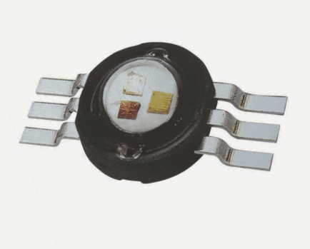
The following image shows a typical 3 watt RGB LED.
According to the datasheet of this LED the three leads on each side correspond with the three leads on the other side on a straight line such that the two straight ends left to right form the terminals of the red, green, blue LEDs embedded respectively inside the package.
Therefore, the upper most left, right end to end leads may form the cathode, anode of the red LED, the center left, right leads may correspond to the green LED, and identically the lower most left, right end to end leads may signify the terminals for the blue LED.
How to Configure the LED Pinouts
Configuring these leads of this RGB LED such that the individual colors can be adjusted separately, is actually quite easy.
The idea is simply to integrate three separate adjustable voltage regulators for these three LEDs, for example by using a LM317 voltage regulator, as shown in the following diagram.
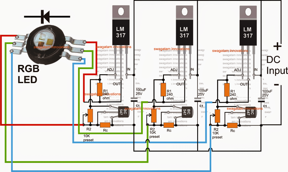
Using LM317 Regulator for the Control Circuit
Referring to the above diagram one can visualize that the three LM317 voltage regulators are in fact exactly identical with their part and wiring configuration.
Each of the modules have the facility of voltage adjustment and are all current controlled through a BC547 transistor and a resistor Rc.
The leads of the 3 watt LED are hooked up individually to the outputs of the 3 LM317 circuits, while the input is fed to all the 3 modules through a common DC source which could be a SMPS adapter rated appropriately for handling the RGB illumination.
The anode, cathode orientation of the LED is also indicated in the diagram which must be carefully and correctly set before connecting them to the 317 outputs.
Once everything is completed, and the power is switched ON, the voltage control feature present in the LM317 modules can be used for setting up the illumination levels of the respective LEDs discretely for creating any of the specified color effects, right from the primary RGB to voilet, indigo, orange, maroon etc etc.
The 10K presets of the 317 circuit can be replaced with 10K pots for enabling an external control for the intended color mixing effects on the LED.
The value of Rc can be calculated by using the following formula:
Rc = 0.6/LED current rating
Simple RGB Color Mixer using Transistors
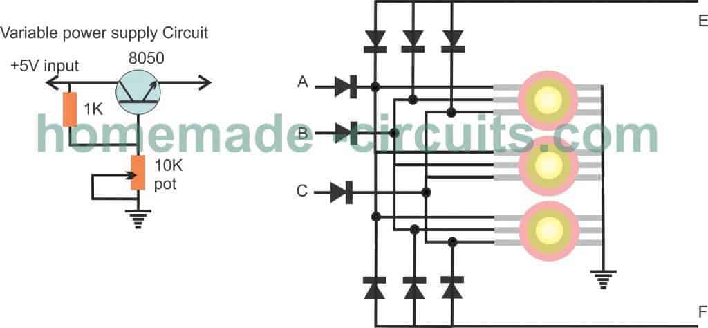
For color mixing, 3nos of 8050 variable voltage power supply could beuilt and their outputs connected with points A, B and C.
For creating fading effect, fading circuit could be connected to point E
For flashing effect point F could be used for supplying the flashing signal.
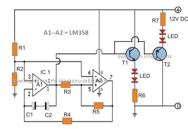
3 Color LED Automatic Color Change
Using this circuit, a multicolored LED may gradually mix and shift across 3 colors. The color transition can be from yellow to red to yellow to green before returning to yellow.
This cycle is then continuously repeated. Both the construction and the theory of operation are extremely straightforward.
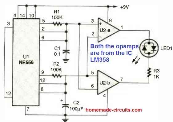
The IC 556 dual oscillator/two timer's timers are set up for astable functioning with a 50% duty cycle. One timer is programmed to oscillate a lot more quickly than the other.
Each timing capacitor voltage is supplied to two comparators, which then apply a voltage to the multicolored LED with a polarity that depends on which capacitor voltage is higher.
The red and green LED components alternately light up as a result of the voltage of the capacitors fluctuating quickly, creating the appearance of yellow light.
The duty cycle is altered to favor one hue or the other as the average value of the slowly varying voltage from the slower timing capacitor alters.
As a result, the change in color appears to be mixing seamless. Hopefully the automatic RGB mixer effect can be utilized in a variety of ways.


Questions & Answers
hello Mr Swagatam for the: Simple RGB LED Color Mixer Circuit using LM317 IC (Pravin), what would be the voltage of the power suply and the Amp? Thank you
Hi Andrea,
For a single LED, the DC voltage must not exceed 9V, amp rating must be higher than the minimum rating of the LED.
Hi. I have a question concerning the transistor circuit. If, instead of the common cathode RGB LED I used a common anode one, how would I have to change the power supply circuit? I also wonder if there mustn’t be any resistors “in front of” the LED input pins and if the 3 diodes are mandatory. And finally, what will become the color of the LED if Red and Green are 0 and Blue goes from 255 to 0; it cnnot be as in color mixing where the color becomes darker and darker blue and finally black. Thanks for any suggestions and help.
Hi, For a common anode LED you will have to use use a PNP transistor based circuits.
Yes you can remove those diodes, they are not required. Limiting resistors might not be required if you clamp the base/ground of the transistors with s 3.3 V zener diodes.
Since black light from an LED is impracticable so it might not be feasible. The end result might a very dark blue dim light. I am just assuming this, I am not entirely sure about it.
Thanks for a really fast answer.
Just to be sure: In the case of a common anode LED, the only thing to do is to use PNP transistors instead of NPN, everything else (including the connections within the power supply circuit) remaining the same? Have you an idea if there is a “standard PNP equivalent” for the NPN 8050?
Have a nice day!
For PNP circuit everything the configuration exactly same as the NPN, except the supply polarity.
For PNP the collector and the 1K junction will go the 0V or the ground supply, while the 10K pot lower end will go the +5V supply input.
The common anodes of the LED will go to the +5V supply and the individual cathodes will to the emitters of the transistors.
The PNP complementary transistor of 8050 is 8550, however you can use any other variant also such as 2N2907 or BD140 etc.
Thanks a lot for your help! You are really kind.
You are most welcome Aly!
RGB in mid to high end computer systems is unavoidable nowadays and many people hate it.
There is seldom a way to set the RGB to a single colour.
(eg: Red for AMD or blue for Intel, white for seeing what you’re doing when working in the system)
If there is; it’s through a bloated, buggy, resource hogging piece of software.
Suggestion/request.
A simple, 3 dial, hardware option that easily plugs into the 5 volt standby power of a computer PSU and to all RGB lighting, fans, etc.
Allowing one can dail in any single colour you desire even when the system is off.
I believe there’s a substantial market for such.
Sorry I could not understand the objective of the design, Why do we need the 5 V from the computer, it can be acquired from any ordinary mobile charger unit. However, a 5 V supply cannot be sufficient for powering RGB LEDs and the fans together…
Hi Swagatam, I have some 3 watt RGB LEDs on a star base that have a common cathode, could you suggest a circuit setup to drive these. I have been toying with a PNP and NPN circuit with an Arduino but wasn’t very successful.
Regards
Geoff
Hi Geoff, could you please specify on what manner or mode would you want to illuminate them?
Hi Swagatam, thank you for your reply. At the moment I only have two of them to play with, so I was thinking of just getting them illuminated as single RGB and then mixing the colours and fading and flashing. These are the specs for them Red: 2.5V ~ 3.0V, 350mA, Green: 3.2V ~ 3.8V, 350mA
Blue: 3.2V ~ 3.8V, 350mA.
Regards
Geoff
Hi Geoff, and how do you want to implement the steps, through automatic sequencing or manually through a switch and potentiometer?
Hi Swagatam, I will be using the switch and potentiometer.
Thanks Swagatam, I will give it a go. The diodes, will 1N4818 suffice?
Regards
Geoff
You are welcome Geoff, since the LEDs are high watt, the diode must be 1N4007 or higher.
Hi Geoff, I have updated a design idea which you could try. If you succeed in building it, please send the video clip to my email, if possible….
hello, would this circuit work for RGB led strip?
yes it can be used with any RGB LED….you just need to set the voltage accordingly
which is the functional range of voltage
set it as per the specs of the LED…input can be minimum 3V higher than the LED voltage spec