In this article I have explained a simple low battery indicator circuit using the IC 555 and a few resistors only.
Circuit Concept
Many electronic circuits such as emergency lights, battery chargers, UPS systems, flashlights etc essentially require a low battery indication feature in order to avoid over discharge of the involved battery. An over discharge could mean a permanent damage to the battery.
A novel little low battery indicator circuit can be learned here, which incorporates just a single IC555 and a few resistors, it's a simple "plug and watch" kind of circuit.
Circuit Operation
The circuit functioning may be understood with the following points:
We all know regarding the basic characteristic of the IC 555 when it's being used in the comparator mode: if pin#2 is subjected to a potential lower than 1/3rd of the Vcc, the output pin#3 goes high.
The above fact also indicates that pin#2 responds with reference to the supply voltage applied at pin#8 of the IC, which implies this voltage at pin#8 should be clamped to some constant level.
Therefore in the proposed design the supply pin of the IC is fixed at some reference level using a zener diode.
The battery voltage is allowed to reach pin#2 of the IC via the preset, which must be manually set such that voltage at pin#2 just falls below the 1/3rd of the zener voltage when the battery voltage reaches the specified lower threshold.
The above setting can be done manually by applying a sample voltage to the circuit imitating the lower threshold level.
Suppose, the specified lower threshold is 11.4V for a 12V battery, the applied sample voltage can be fixed at 11.4V and applied to the circuit.
Next, the preset should be adjusted such that the LED just lights up. Now the preset may be glued by some permanent adhesive for preventing the setting from getting disturbed.
The set circuit is now ready to be attached with the battery in question, whenever the battery voltage reaches the 11.4V mark, the LED would light up, providing the required low battery information.
Simple low battery indicator circuit using IC 555 Diagram is shown below:
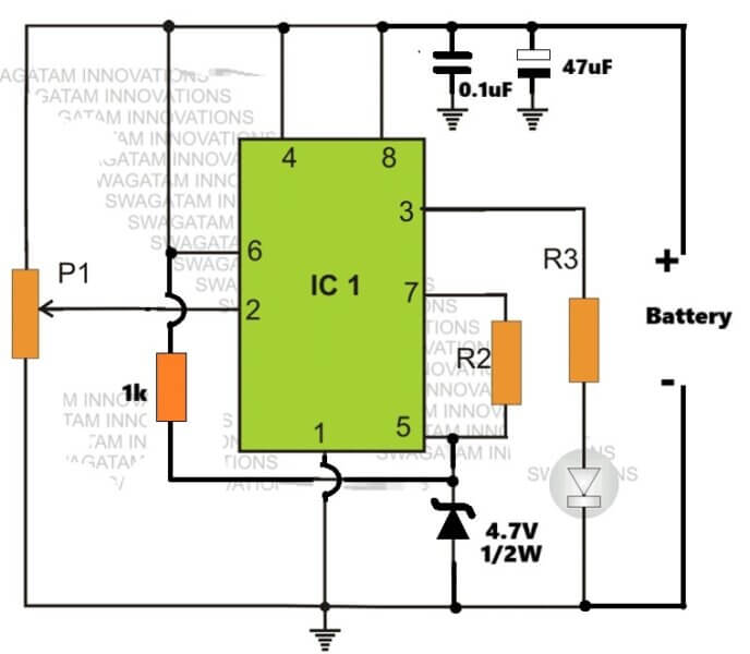
Parts List
R1,R3 = 10K
R2 = 100K
IC1 = 555
P1 = 100K preset
Z1 = zener diode, having voltage lower than the battery voltage.
IC 555 Pinout

555 Low Battery Indicator with Flasher
This 555 low voltage indicator circuit is designed to activate an LED when the power supply voltage exceeds a specific threshold and to make it flash when the batteries require replacement.
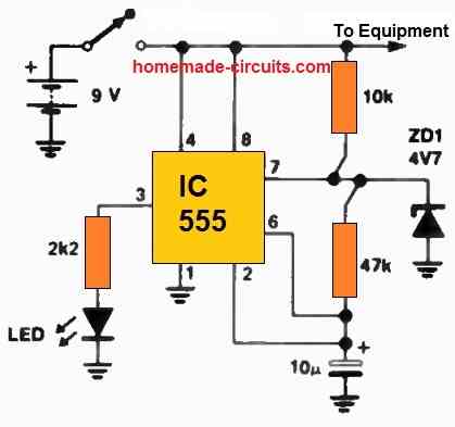
The provided component values are optimized for a 9 V operation. The flashing function initiates at approximately 7.5 V, while the LED won't illuminate at all below 2 V.
The circuit comprises a 555 timer configured in the bistable mode, serving as the driving mechanism for the LED.
The key element here involves connecting a zener diode between pin 7 of the 555 timer and the ground.
During standard operation, pin 7 oscillates between one-third and two-thirds of the supply rail voltage (Vcc). If the voltage at 2/3 Vcc exceeds the zener voltage, it inhibits the 555 timer's functionality.
To adapt this circuit to your specific needs, determine the minimum voltage necessary for proper equipment operation and multiply it by 2/3 to obtain the required zener voltage.
Additionally, you may need to adjust the resistor (R) to match the particular LED you intend to use.
In its original configuration, this indicator circuit drew 7 mA of current at 9 V, decreasing to 5 mA at 7 V.
If these values are potentially problematic for your application, consider using the CMOS variant of the 555 timer, the 7555.
Comments
Sorry, presently i do not have any ideas regarding it, i'll try though.
Hello, my name harry, i want to have fixed circuit using this, for low voltage cut off is under 12.6v and this will switch off the relay, and if voltage rise over 12.7v it will switch on the relay, how to do it? Sorry for my bad english
I have published it here:
https://www.homemade-circuits.com/2013/07/motorcycle-headlamp-battery-over.html
Thanks, i will wait for your circuits 🙂
Hi scientist I'll make a new article for it and post it soon.
Oops, im forgot to click publish for my first post,
Lemme explain,
My motorbike has battery 12v 3ah, and the altenator from this motorbike only use for charging this battery, so all loads in my motorbike using this battery include headlamp, i want making low voltage cut off using ic 555 and relay for the headlamp so when my motorbike idle headlamp goes off since altenator will not charge the battery, voltage battery while idle is 12.6v, and when i pulled the engine, altenator will start charging the battery and voltage raise to upto 15.1v, the headlamp will on, can you help me to make this circuits?
The simple is, circuit will cut off when voltage is 12.6v below and will switch on again if voltage 12.7v above, i already making a circuit from http://www.gorum.ca/lvdisc.html
But that circuit makes relay stuttering (on/off the headlamp like a blitz) i dont like that circuit 🙁
Can you help me to modified or maybe create new circuit that has fixed voltage cut off? 12.6v below will cut off and 12.7v above will switch on, sorry my bad english
I want to using ic 555 because i have stock ic 555 instead of ic 741,
Can i do that?
you can try the second circuit in this ink:
https://www.homemade-circuits.com/2011/12/how-to-make-simple-low-battery-voltage.html
Thanks!
adjust pin#2 volts to 1/3rd of zener volts at 4.2V or below.
add a preset in a similar fashion to pin#6, and adjust it's voltage to 2/3rd zener voltage at 4.3V or above.