In this post I have explained how to make a simple transistor latch circuit using just two BJTs and a few resistors.
Introduction
A transistor latch is a circuit which latches ON with a permanent high output in response to a momentary input high signal, and continues to stay in this position as long as its in the powered condition, regardless of the input signal.
A latch circuit can be used to lock or latch the output of the circuit in response to an input signal and sustain the position even after the input signal is removed.
The output may be used to operate a load controlled through a relay, SCR, Triac or simply by the output transistor itself.
Working Description:
The simple latch circuit using transistors I have I have explained in this article can be made very cheaply using just a couple of transistors and some other passive component.

As shown in the figure transistor T1 and T2 are configured in such a manner that T2 follows T1 to either conduct and or to stop the conduction depending upon the trigger received at the input of T1.
T2 also acts as a buffer and produces better response even to very small signals.
When a small positive signal is applied at the input of T1, T1 instantly conducts and pulls the base of T2 to ground.
This initiates T2 which also starts conducting with the received negative biasing offered by the conduction of T1.
It must be noted here that T being NPN device responds to positive signals while T2 being a PNP responds to negative potential generated by the conduction of T1.
Uptill here the function looks pretty ordinary as we witness a very normal and obvious transistor functioning.
How the Feedback from R3 Works to Latch the Circuit
However the introduction of a feedback voltage through R3 makes a huge difference to the configuration and helps to generate the required feature in the circuit, that is the BJT circuit instantly latches or freezes its output with a constant positive supply.
If a relay is used here it would also operate and stay in that position even after the input trigger is completely removed.
The moment T2 follows T1, R3 connects or feeds back some voltage from the collector of T2 back to the base of T1 making it conduct virtually “for ever”.
C1 prevents the circuit from getting activated with false triggers generated from stray pick-ups, and during switch ON transients.
The situation can be restored back either by restarting power to the circuit or by grounding the base of T1 through a push button arrangement.
The circuit can be used for many important applications, especially in security systems and in alarm systems.
Calculations and Formulas:
Threshold Voltage for BJT Activation
The threshold voltage values for turning ON or OFF the NPN and PNP transistors remain the same:
- NPN Transistor Turn-On Voltage (
VBE(on)):VBE(on) ≈ 0.7V(for silicon BJTs) - PNP Transistor Turn-On Voltage (
VEB(on)):VEB(on) ≈ 0.7V(for silicon BJTs)
These values determine when the base-emitter junction of either transistor is forward biased, enabling current flow and turning the transistor ON.
Base Current (I_B) Calculation
For both NPN and PNP transistors, the base current is still calculated in relation to the collector current:
- Base Current for NPN Transistor (IB(NPN)):
IB(NPN) = IC / βNPN - Base Current for PNP Transistor (IB(PNP)):
IB(PNP) = IC / βPNP
Where:
ICis the collector currentβis the current gain of the transistor (typically 50–300)
This is relevant for understanding how the transistors maintain their ON or OFF states once latched.
Collector-Emitter Voltage (V_CE)
The voltage across the collector-emitter junction of each transistor is very important for ensuring the transistors remain in the active or saturation regions:
- NPN Transistor Saturation Voltage (VCE(sat)):
VCE(sat) ≈ 0.2V(when fully ON) - PNP Transistor Saturation Voltage (VEC(sat)):
VEC(sat) ≈ 0.2V(when fully ON)
These values are relevant when the latch is "set" or "reset," which ensures that both transistors are either fully conducting or completely turned off.
Latch Holding Condition
Once the latch is set or reset, the feedback ensures that the state is maintained regardless of the input signal:
- Feedback Current (IFB):
IFB > IB(required)
Where, the IB(required)
This feedback signal ensures that once the NPN or PNP transistor is turned on, the circuit remains latched in that state until forced to reset.
Resistor Calculations
Resistors will control the currents flowing through the transistor and define the behavior of the circuit:
- Base Resistor (RB):
RB = (Vinput - VBE(on)) / IB - Collector Resistor (R_C):
RC = (VCC - VCE(sat)) / IC
Where:
Vinputis the voltage applied to the base of the transistorVCCis the supply voltageIBandICare the base and collector currents, respectively
These resistor values help in controlling the current levels to properly switch and latch the circuit.
Switching Time
The switching time for the latch circuit or the time it takes for the latch to change states is determined by the charging and discharging of junction capacitances:
- Rise Time (tr):
tr ≈ (RB * Cj) - Fall Time (tf):
tf ≈ (RC * Cj)
Where Cj is the junction capacitance of the transistor which determines how quickly the transistor can switch between states.
Hysteresis Voltage
Hysteresis ensures that once the circuit is latched in a particular state... it remains stable:
- Hysteresis Voltage (Vh):
Vh = IFB * Rfeedback
Where:
Rfeedbackis the feedback resistor value.
This feedback voltage creates a gap between the switching thresholds which helps to prevent oscillation and ensurs stable operation.
Testing procedure can seen in the following video tutorial:
Parts List
- R1, R2, R4 = 10K,
- R3 = 100K,
- T1 = BC547,
- T2 = BC557
- C1 = 1uF/25V
- D1 = 1N4007,
- Relay = As preferred.
PCB Design
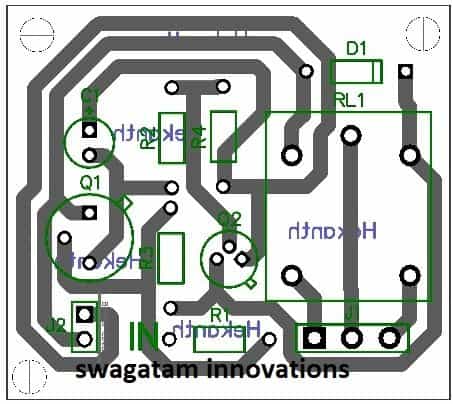




Discussion & Solutions
Hi Swagatam
I have used this latch circuit in my projects.
Recently, I came across more simpler but identical circuit which does not has C1, R2 and R4. Instead a 1K resistor is there in place of C1.
Just want to know what is the difference between the two circuits in terms of function/performance.
Hi Abu-Hafss,
No difference at all, the above circuit can be simplified to much greater extents, I have just provided the basic or the standard design here.
Hi Swagatam
The INPUT of this latch circuit is very very sensitive.
1) Sometimes the latch triggers when the input is touched with finger.
2) Sometime it triggers when the circuit is powered on thru a mechanical switch. It seems that when the switch is switched on, some signal is induced within the circuit which causes unexpected triggering of the latch.
How can we sort out these problems?
Hi Abu-Hafss,
Increase the value of C1 to 10uF or more, the problem will be solved.
Hi Swagatam
Can i use a polarized capacitor in this circuit?
Hi Vasilis,
I think you won't need this additional circuit, because your pellet burner first 555 stage is itself a latch. You can add another BC547/relay stage with this existing monostable and invert the response. The base of this new BC547 stage can be connected with collector of the monostable BC547 via a 10k resistor. As soon as the monostable time lapses, the new stage relay would get activated for the intended actions.
…to answer your present question: Yes, a polarized capacitor of any higher value can be used in the above design.
Hellow sir, can you please help me
I want a simple latch circuit that holds the output signal for about 100 Seconds.
I have tested timer circuit using CD4060 but didn't get my requirement, the result was ON time for 100 s and OFF time for the nearly same time, thereby output voltage again becomes high after 100 s.
I am in the middle of constructing a simple water level controller. My intention is to fill my home water tank with water from a ground storied small water tank. The water from public water connection is being filled in the ground storied tank. So when the water level in that tank raises to its maximum i want to activate the motor automatically and then turn off the motor after 100 s again starting the motor when water level begin to overflow the lower tank.. This should be continued till the overhead water tank just begins to overflow…. So i want a latch circuit for 100 s
Hello Deva, you can try the circuit which is explained in the above article.
Just connect a 220uF series capacitor with R3, and make R3 = 2.2M
Now whenever the input trigger is connected to positive via water, the relay will activate and the circuit will latch until the 220uF cap is fully charged after a predetermined delay.
The delay will depend on the values of the 220 cap ad R3 which needs to be adjusted for getting the 100 seconds delay.
Sir i saw your reply at morning. I have changed the logic of filling the upper tank in another way compared to that said at last night. I have told you last night to help me in placing a logic for counting the number of times the lower tank is being filled with public water and thereby inhibiting the condition of overflow of the uppper one. Now i want to place a different logic that, whenever the overflow condition is detected once in the upper tank, i have to inhibit any future activation of the motor even the pin#2 of 555 gets lower threshold ( during overflow in lower tank )….. Expecting your suggestion soon sir
Sir i have succeeded with ic 4060. A 555 ic has been used for generating the main logic. According to my design, when pin#2 of ic 555 gets low voltage output pin#3 becomes high which then switches on the transistor connected to this terminal. I have connected the timer stage in between +12 V and the collector terminal of this transistor, hence the timer stage is switched on when the pin#3 of 555 becomes high. pin#6 of 555 has been connected to pin#3 of 4066, so when timing lapses (100s ) makes this pin high, resulting in low value at the output pin of 555 also the timer stage….. The logics at these terminals ( 2 and 6 ) hence thereby used to establish the necessary turning on and off the motor.
Now i am in dilemma, plz help me sir.
According to ma diagram, motir switches on whenever the water overflows in the ground storied tank and switches of whenever time elapses or the overhead tank overflows…. But this continues till water stops in public water tap…. but, always my overhead tank overflows by second stage of pumping water from the ground storied one. So i want a slight change in this circuit that, after detecting an overflow in the overhead tank the motor shouldn't be turned on untill a next manual activation is detected
Sir a simple doubt,
How this latch can be made disabled once it is activated ?
I mean without turning of the supply..
I couldn't disable it after activating the latch even connecting a low voltage as threshold
Deva, I'll need a diagram to understand the problem, without the diagram it will be difficult to solve the issue.
You can send the diagram to my email, if possible I'll check it.
Sir you email id plz?
Deva, it's given in the contact page, see top section.
Sir ,
I have sent the circuit to both the emails given in the contact page. Plz go through your inbox
not found,, checked both emails, not even in junk folder.
No way sir. I am tired of checking my circuit many times after soldering…..
Circuit is said to be fine, checked by you and me. No problems detected during in bread board. But i can't identify what is happening when it has been moved into the PCB.
The IC3, IC4 stages and thereby relay are switched on when power reaches IC1. This didn't occur while testing in BB. According to my design these stages are switched on whenever the sensing nodes dipped in the lower tank ( A and A' ) are shorted by overflowing water, but what to say it is turned on even initially on powering the circuit. All the connections are examined, no errors found. Everything is perfect.
The circuit is completely formed by me, thereby may error occurs. Can you identify anything after arranged in PCB SIR ?
You can connect LEDs in series with the bases of the transistors, this will give you the indications regarding the relevant triggering.
You can also try testing the stages separately, by cutting the PCB tracks between the stages and by checking the response of individual stages with manual triggering.
Sir,
Could you please suggest me a circuit, the output of which should go high for programmable ON time and when the time lapses turns the output to zero permanently untill a next manual trigger is applied.
I have searched many timer circuits, but majority of them have ON time as well as OFF time yielding the output to turm ON again when OFF time lapses
Arun, you can try the circuits shown in the following article:
https://www.homemade-circuits.com/2012/01/how-to-make-simple-versatile-timer.html
The power to the circuit may be provided from any 12V dc adapter instead of the shown capacitive power supply.
Sir i have sent to you a modified version of the previously presented circuit. Would you mind checking your both emails ? I have some doubts regarding it. Expecting a satisfactory reply soon
Sir, is it possible to fed the Neutral line of ac supply instead of phase line to the centre terminal of the relay, in order for safety
I have checked the diagram, it looks similar to the previous one.
Yes, the phase or the neutral either of the lines can be used with the relay for getting the cut offs, however connecting the phase to the relay or any switch is recommended.
Atlast i got it sir. Since all the problems were seen to occur while connecting the relay stage, i thought that some types of backward emf is flowing from the relay to the preceding stages, so i have disconnected the wires feeding control voltage to the relay and connected two diodes (1N4007) as shown below which has solved the issue to an extend.
Possitive wire …….-|>|………Relay possitive terminal
Negative wire………|<|- ………….Relay negative terminal
But my doubts are
1). What is the cause for this back emf
2). whether this could be taken as a permanent solution or whether i have to chose any other back emf protection circuits, if i have to could you please suggest me one
Deva, in your circuit you already have one diode installed across the collector and positive of the transistor which is used for triggering the relay and the 4060 stage….so back emf cannot be the issue.
The issue could be with the 555 IC1 and IC2, which needs to be identified patiently or better be replaced with transistorized set/reset circuit.
Sir,
what must be the correct specification of the relay to be used with a 0.5 HP pump motor ?
I have corrected all the problems and the entire circuit was found working perefectly on loading with a table fan, but when it was loaded with my 0.5 HP motor, water had not been pumped to the tank ( indicated by the drain motor section, also verified by physical examination ). Water flowed as there was an obstacle which restricts the pumping action also the entire circuit was seemed to be loaded…
The written things on the relay i have used are shown:-
50/60 Hz
7A 250V ~ 10 A 125V AC
12A 120V – 10 A 28V DC
Arun, the relay is OK,
try operating the circuit/relay through a 12V battery and see if the problem persists or not.
If still it behaves the same way, we can try isolating the relay power supply by employing a separate external DC for the relay/4060 sections.
Sir it is nof the problem due to relay. I got my motor working when an external 12 V trigger has applied. So what will i do now ?
I know i am disturbing you much. but what to do, i will have to complete this anyway
Sir, i forgot to say some last modifications done. I have again connected 1N4007 in between +12 V and the collector of output driver transistor also a 100 uf/25V capacitor has also been connected in b/w these terminals. These modifications eliminates the fast repeating sound of the buzzer BZ1 and made it functioning well. I have disconnected the relay feeding voltage terminals from this output driver stage and used a simple MOSFET( IRF540 n ) switching circuit to control the relay voltage. A 1N4007 and a 12 V , 1W zener diode are connected( in phase to phase ) in between the relay control voltage terminals ( MOSFET stage ) as a flyback. I will try to send this to your emails.
Arun, I could not understand what's the exact problem with your circuit…I thought as soon as the motor is being switched ON by the relay the circuit is getting disturbed and not giving the required results…is it so??
…I could not understand why you have so many parts, diode, zener diode, mosfet….all these have no relevance to the circuit functioning.
Just one diode across the relay coil is all what is needed.
Exactly the problem what you said sir.
The circuit is getting disturbed as soon as the motor is turned on automatically and not giving intented results. But the same works perfectly when a table fan is connected in place of the motor.
Since the driver transistor drives so many stages such as CD4060, buzzer indicating motor running, also the relay i thought that there are some disturbances arising to these stages due to problems in relay stage since they are all under same section. Hence i decided to drive the relay on a separate stage thereby chose the MOSFET switching stage. On searching internet about flyback problems faced by relays, i found a config. ( as shown in the diagram as the combination of diode and zener in phase to phase ) which nest suites for relays in terms of avoiding transient suppressions and retaining long life. So i used it.
And about the extra capacitors used :-
When unexpected beaping sounds from the buzzer i just put a 100 uf capacitir across the driver terminals in theintention if avoiding any nuisance signals, by a luck i got succeeded. I have repeated the same in relay stage also. These are to say about the extra components.
Now i think you could get my problem which is exactly same as you thought.
Everything i needs now is a perfect solution for this.
Expecting that soon with a good mind
The problem is not due to relay coil back-emf, it's due to the pump motor winding back emf and transients that's causing the problem. The motor could be sending strong back-emfs over the entire housing wiring.
As you have said that when you connect a fan or any other load, the circuit behaves fine….just switch ON the pump motor externally while the fan is connected, and check whether the fan gets rattled or not.
If not it would mean that if the relay stage is isolated using a optocoupler could solve the problem….if the problem is witnessed then probably you'll have to get rid of the IC555 stages and replace them with other alternatives.
Latest news:-
I hav tested the circuit by connecting an another similar relay used to give an external 12 V supply to the motor driving relay. The new relay is controlled by the voltage from the output transistor driver stage. Thereby overall the motor has been isolated from the driver. Now i got thr motor functioning. So what should i have to understand from this ? Is that the problem caused by the high back emf associated with thr motor as you said
Or
the problem due to 555 stages ?
If the high back emf may be the real reason, i think the whole home wiring would have been get affected from this atleast the Refrigerator kept operated near it would have been affected. But ni such problems are there in connecting the motor as usual
The 555 IC stage cannot be compared to a refrigerator, because the 555 is an electronic stage consisting of analogue circuitry which can be vulnerable to noise and transients.
Try replacing the 555 with (7)555, these are same as 555 ICs but are CMOS versions which are entirely resistant to external noises and disturbances.
Now i have understood that all those problems were due to high transients from the motor as you said earlier, coz the circuit isfunctioning properly even on a mixer grinder…. So nothing to worry about 555 stages.
Now my doubts are:
1). Why the mixer grinder didn't produce transients eventhough it is basically an induction motor ?
2). How to chose an optocoupler or
Whether a bidirectional Transient Voltage Suppression (TVS) diode will solve it ? If it can, what specification of it to be chosen???
3). Is there are any other simple transient suppression circuits?
Expecting your reply soon
1) mixer grinder is too small compared to a 0.5 HP motor.
2) The switch ON transients from the water pump motor could travel throug the air also and could be easily picked by the opamps inside the 555, so I don't think it can be stopped by any means.
Sir also, if i am gonna use a MOV or TVS diode or suitable RC network to suppress high transient spikes, how they can be connected to the present circuit ? I could understand that one terminal connected to the ac L line. Where the other end to be connected ? To Neutral or Ground ????? OR to the N/O terminal of the relay?????
requesting not to forget to say the the specification of TVS or MOV suitable for this circuit if is gonna used……….
According to me MOVs or any such device won't help, as mentioned earlier you can try replacing the ICs with (7)555 ICs or other CMOS alternatives.
In the latch circuit given in this article, the output voltage (latched voltage) reduced when the feedback resistance 100k is connected. I have used 12.4 V to supply the circuit, but got only 11.3 V something as the output voltage. When it has been checked keeping the feedback resistance disconnected i got full voltage. Tried with different valuee of resistances, but same was the results. In the circuit i requested before, i need full voltage as output and should have a default on stqte and should latch in low state when a trigger is applied. Could u plz help me sir??????
Sir,
Could you plz suggest a transistor or other circuit that holds its output at high when power is applied and turns its output to low when a trigger is applied
Sir, in the circuit i requested before, the output should go low permanently when a trigger is applied
Usha, You can try the above circuit….take the output from the collector of the NPN transistor for getting the specified results.
……the relay may be removed and replaced with a 100k resistor.
Thanks sir. I got it. Now can you provide me a ' ON after 2 s delay ' circuit using transistor
please refer to the following design:
https://www.homemade-circuits.com/2013/02/make-this-simple-delay-on-circuit.html
Hellow sir deva again. I was busy with some other works for the last 3 days, thereby couldn't update the results. Now i am entirely changing my circuit replacing the 555 stages by transistir set/reset circuits as you said earlier. I have skipped all unnecessary components such as mosfets, zener etc. from the previous design. Now i am here to seek for any options available for storing a single state even after power failure. I asking you such an option, coz i need to modify the circuit by adding the facility that it SHOULD PROVIDE US THE CURRENT STATE OF ACTION i.e, it should indicate a low iff the overhead tank had overflowed and should show a high state if it is under processing ( tank not overflowed ). This state shouldn' t fluctuate with any external disturbances such as power failure etc. That is, if it had shutt off it should remain shut off even aftr power reaches after a failure. I have designed such a one. But it is less effective. Couls you please put a look at that. I have sent it it your mails
Sir when i am connecting the relay as shown in the latch circuit given in this article, the voltage at the output is getting reduced to 6 or 8 V. I have also tried by driving the output stage with a transistor. But no change. What 2 do ?
I have used an another NPN transistor for reset purpose.
Sir i am waiting to hear your valuable suggestion about the problem of reduction in voltage by connecting the relay