This 150 watt amplifier is designed to provide a full 150 watt peak to peak music power amplification over a 4 ohm loudspeaker.
In this post I have explained how to make a simple 150 watt power amplifier circuit using a typical OCL design which ensures cheap layout and use of minimum components, with high reliability.
Introduction
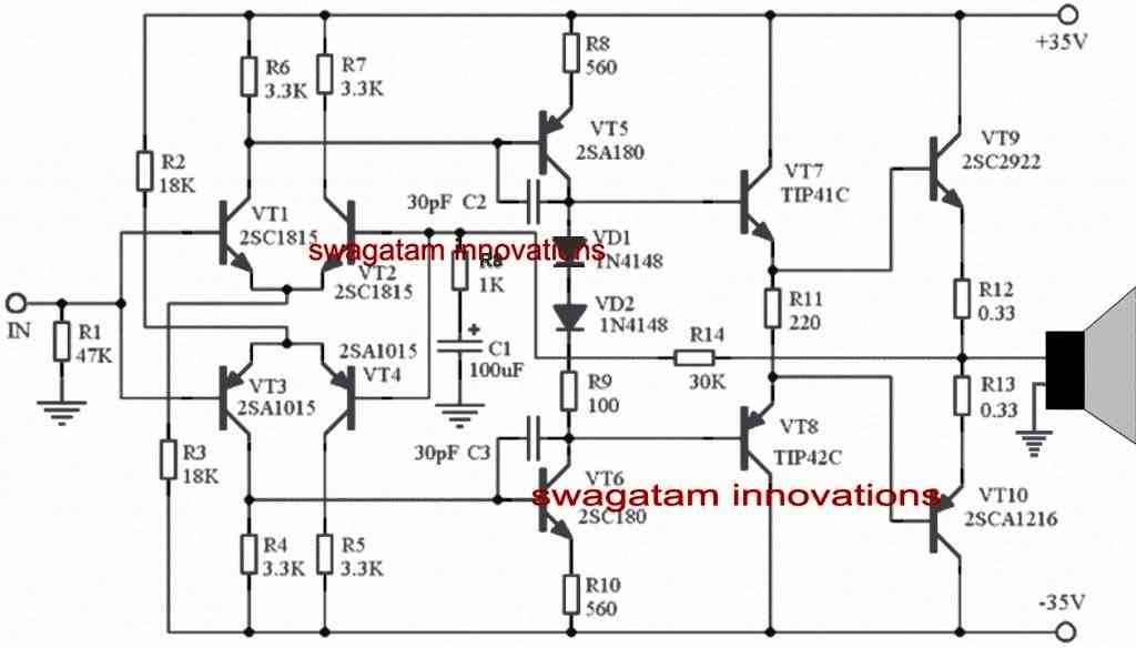
Referring to the figure a perfectly symmetrical OCL based amplifier can be seen , using discrete components suitable for all electronic enthusiasts and hobbyists for going through an in-depth practical study with its topology.
This OCL amplifier circuit is a mid-range power amplifier capable of delivering a good 150 watts of power due to its symmetrical structure, wide frequency response, simple layout and so on. The sound quality will be quite satisfactory, and comparable to other equivalent high-fidelity amplifiers normally preferred by the users for home use.
How the amplifier circuit works
The first stage of the circuit can be seen built with a complementary symmetrical differential configuration, each of the BJT channels using 2SC1815, 2SA1015 consume about 1mA, while in the quiescent state
The next stage is designed for handling the voltage amplification and this also makes use of a complementary push-pull design, through a set of high power complementary pair of BJTs namely A180, C180, which runs using a current of about 5mA.
The two 1N4148 ensure a drop of 1.6V required for biasing the relevant bases of the complementary BJTs.
The next two complementary power BJTs involving TIP41C, TIP42C create the driver stage or the intermediate buffer stage fo the last power transistors.
The inclusion of this high efficiency buffer/driver stage becomes one of the main features of the modern OCL amplifier design, which helps to offer a high load impedance, and thereby ensures a very stable Higher gain amplifier output stage.
Additionally this type of capacitor less topology also ensures a lower output resistance across the output power transistor stage, which in turn helps the output junction capacitance Cbe charging rate to become faster, thus improving the overall transient characteristics and frequency stability of the circuit.
However the operating current of this stage can be slightly higher, at around (10-20) mA, for each of the channels which may sometimes go as high as 100mA under higher full volume, this happens because the specified quiescent current may be capable of saturating the output stage to the most optimal levels.
As can be witnessed in the given 150 watt amplifier circuit diagram, the emitter resistances of the driver stage employs a floating termination, and these are not connected with the earth line, and this causes the amplifier to operate typically in the Class A range, and ensure a maximum bias voltage for the output stage.
The power output stage is wired using the traditional complementary capacitor less design and features an FT (frequency transition) level of as high as 60 Mhz, across the BJTs C2922, A1216, through a quiescent current consumption of around 100mA.
The amplifier also employs a negative feedback loop across the output stage and input inverting stage, which sets the amplifier to a gain level of approximately 31.
Part Equivalents
If you find it difficult to get the parts mentioned in the diagram, you could replace them with the following equivalents.
- VT1, VT2 = BC546
- VT3, VT4 = BC556
- VT6 = MJE340
- VT5 = MJE350
- VT9 = TIP3055
- VT10 = TIP2955
How to Convert into Higher wattage Power Amplifier
The title of the article suggests that the mentioned design is intended for delivering 150 watts of power, but in reality the specs are actually never restricted for such designs. You can easily upgrade the circuit to produce much higher outputs simply by increasing the voltage upto 90V.
The power devices mentioned in the above parts list are specifically selected to handle higher voltages and to enable the required upgrades.


Comments
Hola Sr. Swagatam, quiero preguntarle si me puede enviar el diagrama eléctrico de la fuente de alimentación del amplificador y que sea para 120v al transformador, sería de gran ayuda que la fuente sea de 120v, Gracias.
Hello Mr Swagatam. I would like to know if the VT6 is a mosfet or bjt transistor, since I have looked for the datasheets and I have not found information about them; Thank you.
Hello Miguel, it is a bipolar transistor. You can replace them with similar equivalents by referring to other equivalent amp circuits
Hello Mr. Swagatam, do you have any PCB designs to mount and solder? I am starting in electronics and I do not want to damage anything and if you also have some design of the source that in turn feeds an asymmetric preamplifier, Thank you. (The mail is real).
Hello Miguel, I think you should try the following design instead, which has all the required details along with the PCB design:
https://www.homemade-circuits.com/how-to-make-simplest-100-watt-mosfet/
It is a thoroughly tested design also…
TIP 41C & TIP42C substitute
MJE340, MJE350
I have a question . This circuit do not need a zobel network ??? . Answer me please . Thank you . Pedro .
It is optional, if you want you can add it yourself…
what is the value of VT10 sir? Thank you.
tda 2050 datasheet says max +-25 v dc—this is regulated or unregulated dc voltage ???
—-i am using 16-0-16 v transformer after rectification,filter caps gives 22-0-22 v dc(non regulated)=44 v —which when load speaker connected surely drop voltage to 16-0-16 v on load=32 v (not measured best guess)
——–so what do you think i should get a transformer which when load applied should give 50 v ?
———thank you
25V is the regulated value and should not be exceeded.
22V is OK, so you can use 0-16V taps and use it with a bridge rectifier and filter for operating the amp.
However if the voltage is dropping that indicates your transformer is low in current and you must replace it with a higher rated transformer that will suit your amplifier specs.
thanks——–
tda 2050 gives 16 v rms at 3.5 a for 4 ohm load—see the video—in 10:10 timing—
https://www.youtube.com/watch?v=4w2__5rWANE
—actually my point of view is whenever we apply unregulated transformer power to amplifier——-voltage will drop obviously—
example —-16-0-16 v after rectifier filter caps becomes 22-0-22 v dc unregulated—under load drops to 15-0-15 v dc=30 v dc————
so to meet +-25 v dc requirement i have to apply approx 21-0-21 v ac transformer
then why people recommend 16-0-16 v ac transformer for amp tda 2050 that has +-25 v dc max — in all forums i have seen ?
Voltage will drop if the filter capacitors are not strong enough and incorrectly rated.
here 16V is the RMS value of the transformer and 22V is the peak value, which will be maintained if the filter capacitors are calculated correctly.
25V could be the absolute maximum value which should be avoided, so 16V to 20V is the optimal value for operating the IC.
in 3 way tower speaker——–how calculate——–impedance/resistance——–
i have
4 ohm–woofer—4 ohm—mid—12 ohm—tweeter—-
crossover—4 ohms
when i measure resistance after connecting long speaker wires approx 10 ft—i measure 10 ohm
——-what do you think to measure impedance/resistance ?
———–thank you
Measure it directly across the speaker terminals…
according to me long wires will affect the power output, because music carries high frequency which can get affected with slight rise in wire resistance, and the amplifier should be connected close to the speakers for optimal response.
ok thank you
Dc or Ac operation?
DC
Thanks for the quick reply sir.can i use a 4ohm subwoofer on this amp?god bless you,sir.
you are welcome Noel, yes you can use a 4 ohm subwoofer with this amplifier design.
Good day,sir swagatam.can i use this amp in a bridge mode type?and how to do that?how much power will it deliver using same power supply @ 4ohm load.
Hi Noel, you can probably do it, however I am not sure how exactly it may done because I have never tried it so far…
Well done sir, but there’s something missing on this circuit which we have to add as follows;
There should be a resistor of 3.3K ohms between the base of transistor 2SC180 and the +35V rail and the same should be done to the transistor 2SA180
Thanks Kakooza, but how do you confirm your suggestions are correct? To me the circuits looks perfect…
Me puede dar el circuito en PDF para imprimir y apricarlo a la baquelita con en metodo de planchado del amplificador de 150 wts. Gracias
¿Te refieres al diseño de la pista de PCB? Intentaré subirlo pronto.
Thanks sir for this circuit but how can I change the value of resistors to accommodate a supply of 80V-0-80V DC
kakooza, you don’t have to change anything for 80V supplies also…you can try it.
how can i amplify the power to get up to 250 watts instead of 150 watts
by increasing the supply voltage