• Skip to main content
  • Skip to primary sidebar

Homemade Circuit Projects

Need circuit help? Post them in the comments! I've answered over 50,000!

Blog | Categories | About | Contact | Calculators-online
You are here: Home / Audio and Amplifier Projects / OCL Amplifier Explained

OCL Amplifier Explained

Last Updated on May 5, 2022 by Swagatam 6 Comments

In the field of audio amplifiers OCL stands for Output Capacitor-Less Amplifier design.

Table of Contents
  • How it Works
  •  Circuit Example
  • Advantages

How it Works

In this OCL type of amplifier topology or configuration, the power output stage is directly coupled to its preceding driver stage without coupling capacitors.

The following figure shows a typical OCL amplifier output stage, as can be seen, the VT9/VT10 power BJTs bases are directly linked with the VT7, VT8 BJT stage, and the same can be seen with the earlier stage, wherein no capacitors are involved for the indicated couplings.

 Circuit Example

OCL Amplifier

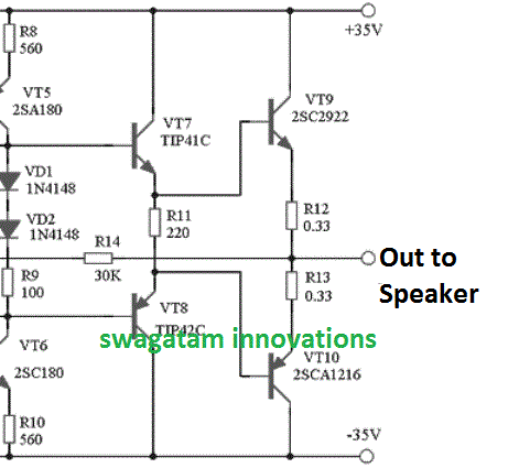
Although there could be many versions of OCL amplifiers, mostly the push-pull type output configurations is popularly employed in OCL designs. as shown above.

Advantages

The OCL configuration could become popular due to some distinct advantages it possesses, compared to the other forms of amplifier topologies. The main features can be learned from the following points:

  • Elimination of capacitor coupling enables the unit to become very sleek and compact, and also helps to make the design very cost effective.
  •  The OCL design ensures enhanced immunity to the so called "motorboat oscillations" in amplifiers.
  •  The design also allows the unit to deliver high power outputs even at lower input audio frequencies or DC supplies.

Disadvantages

Although OCL amplifiers come with a few great advantages, it may exhibit a couple of marked disadvantages, as given below:

  • The power devices show a tendency of dissipating significant amounts of power.
  • In amplifiers where the bias points are poorly controlled, an OCL amplifier could pass the DC content into the loudspeakers, causing heating of the loudspeaker.

You'll also like:

  • 1.  Amplifier Short/Overload Protection Circuit – 2 Ideas Discussed
  • 2.  Loudspeaker Thump Sound Eliminator Circuit
  • 3.  Simple Stereo Amplifier Circuit Using IC TDA1521
  • 4.  Parametric Equalizer Circuit
  • 5.  How to Make an Outstanding Home Theater System
  • 6.  Explained: MAX4466 Electret Microphone Amplifier Module with Adjustable Gain

About Swagatam

I am an electronics engineer with over 15 years of hands-on experience. I am passionate about inventing, designing electronic circuits and PCBs, and helping hobbyists bring their projects to life. That is why I founded homemade-circuits.com, a website where I share innovative circuit ideas and tutorials. Have a circuit related question? Leave a comment.... I guarantee a reply!

Previous Post: « Automatic Irrigation Circuit using Arduino
Next Post: Simple 150 Watt Amplifier Circuit using Transistors »

Reader Interactions

Comments

  1. wilfredo dorosan says

    January 28, 2020 at 11:57 am

    sir are you also the maker. of. socl. boom. tef which. is powered up. to 90vdc can you teach me how to make. it 140vdc without dc output stable with 12 output power. transistor of 2sc5200 and 2sa1943 thanks you

    Reply
    • Swagatam says

      January 28, 2020 at 4:24 pm

      Sorry wilfredo, I have no idea about this concept!

      Reply
  2. Claude says

    August 28, 2019 at 6:41 am

    Your article replacing the BJT with Mosfet could be misleading regarding enhancement mode Mosfets.
    The BJT base – emitter resistor cannot be removed using a enhancement-mode mosfet for bias but certainly with a depletion mode device because its self biased nature for small signal applications.
    Perhaps you can share your knowledge with a small signal common gate single stage preamp design of low distortion with a gain of about 3-5 inputting a direct coupled 30- 45 ohm input source for my laptop.
    I will take care of the output loading to the following stage.
    The enhancement mosfet would be a BS 170 at about 2-3 ma of drain current.
    A attached file design would be greatly appreciated.
    Love your designs and articles.
    Claude…

    Reply
    • Swagatam says

      August 28, 2019 at 7:50 am

      Thank you, however I could not find where I wrote that the base/emitter resistor should be removed while replacing BJT with MOSFET?

      I am not good with designing preamps or amps so can’t precisely suggest the circuit you are looking for, however I have an extensive article regarding preampms under the following link, hope this helps:

      https://www.homemade-circuits.com/small-amplifier-circuit/

      Reply
  3. Sreekumar K says

    October 2, 2017 at 3:55 am

    Could you please send the PCB layout of your circuit 100w power amp using 2N3055 transistors?

    Reply
    • Swagatam says

      October 2, 2017 at 4:09 am

      I have the entire design in an old elektor electronics magazine, if possible will try to publish it soon….

      Reply

Need Help? Please Leave a Comment! We value your input—Kindly keep it relevant to the above topic! Cancel reply

Your email address will not be published. Required fields are marked *

Primary Sidebar

Subscribe to New Circuit Ideas

Categories

  • Arduino Projects (87)
  • Audio and Amplifier Projects (132)
  • Automation Projects (17)
  • Automobile Electronics (101)
  • Battery Charger Circuits (83)
  • Datasheets and Components (104)
  • Electronics Theory (143)
  • Free Energy (37)
  • Games and Sports Projects (11)
  • Grid and 3-Phase (19)
  • Health related Projects (25)
  • Home Electrical Circuits (12)
  • Indicator Circuits (14)
  • Inverter Circuits (87)
  • Lamps and Lights (142)
  • Meters and Testers (69)
  • Mini Projects (46)
  • Motor Controller (64)
  • Oscillator Circuits (27)
  • Pets and Pests (15)
  • Power Supply Circuits (108)
  • Remote Control Circuits (50)
  • Security and Alarm (64)
  • Sensors and Detectors (101)
  • Solar Controller Circuits (59)
  • Temperature Controllers (42)
  • Timer and Delay Relay (49)
  • Transmitter Circuits (29)
  • Voltage Control and Protection (37)
  • Water Controller (36)

Calculators

  • Battery Back up Time Calculator
  • Capacitance Reactance Calculator
  • IC 555 Astable Calculator
  • IC 555 Monostable Calculator
  • Inductance Calculator
  • LC Resonance Calculator
  • LM317, LM338, LM396 Calculator
  • Ohm’s Law Calculator
  • Phase Angle Phase Shift Calculator
  • Power Factor (PF) Calculator
  • Reactance Calculator
  • Transistor Astable Calculator
  • Transistor base Resistor Calculator
  • Voltage Divider Calculator
  • Wire Current Calculator
  • Zener Diode Calculator
  • Filter Capacitor Calculator
  • Buck Converter Calculator
  • Boost Converter Calculator
  • Solar Panel, Inverter, Battery Calculator
  • Wire Current Calculator
  • SMPS Transformer Calculator
  • IC SG3525, SG3524 Calculator
  • Inverter LC Filter Calculator

People Also Search

555 Circuits | 741 Circuits | LM324 Circuits | LM338 Circuits | 4017 Circuits | Ultrasonic Projects | SMPS Projects | Christmas Projects | MOSFETs | Radio Circuits | Laser Circuits | PIR Projects |

Recent Comments

  • Swagatam on Real MPPT Solar Charger Circuit Using Arduino, LCD, and Manual/Auto Switch
  • Obaidullah Khan on Real MPPT Solar Charger Circuit Using Arduino, LCD, and Manual/Auto Switch
  • Swagatam on 2 Compact 12V 2 Amp SMPS Circuit for LED Driver
  • Alan Bishop on AC Motor Speed Controller Circuits using Back EMF
  • Swagatam on Real MPPT Solar Charger Circuit Using Arduino, LCD, and Manual/Auto Switch

Company

  • Privacy Policy
  • Cookie Policy
  • About Me
  • Contact
  • Disclaimer
  • Copyright
  • Videos
  • Sitemap

Social Profiles

  • Twitter
  • YouTube
  • Instagram
  • Pinterest
  • My Facebook-Page
  • Quora
  • Stack Exchange
  • Linkedin
  • © 2025 · Swagatam Innovations