The article is a continuation of the earlier post where we tried to find a solution for creating unique infrared IDs for trains in a model locomotive system. Here I have explained the application in detail and learn how it may be possible to successfully implement the idea using tuned IR detector circuits. The idea was requested by Mr. Henrik
Technical Specifications
Dear Swagatam,
Why don’t you live in Ribe, Denmark or me in India. Would make it all much easier :o)
Since we have at least 50 locomotives and more will come I am sure. The idea of implementing 50 units on each train station track won’t work, but maybe we could decrease the amount of circuits on each track by letting only some trains pass on eg. track 1 and some on track 2 and so. I will talk to my son about that.
The ideal solution would be to know exactly where every locomotive would be on the tracks. Some modules from the big companies use RF or the digital signal through the tracks to inform the position of the trains. The only bad thing about their modules is the price.
Most people have a small track with a few locomotives and can easily run the model trains manually. Ours is too big and keeping track of 50 trains is not human possible.
Therefor we have developed a software to help us. The software though needs some inputs to act as I mentioned earlier. All the inputs to the software comes from S88 modules (special developed to model train track by some German company), USB and parallel I/O circuit boards.
This brings me to another point where you maybe could have an idea.
I have made a small circuit to turn on/off transistors to switch a relay or something. Do you have an idea to a homemade USB circuit with input / outputs? I need a lot of input /outputs for our computers.
Now to the way the trains stop, slow down and accelerate. All trains are equipped with a digital controller and through the track receive information to accelerate, stop, turn on lights etc.
Our software sends these commands through a digital controller unit from Märklin (Märklin 60212) connected via LAN.
All these info is just to inform you how things works for the model trains.
So to stop a train I would send a command from any computer in our house or manually by selecting the ID of the train and tell it to stop from the 60212 command unit.
The RX module is the receiver right? If yes then they should be under the tracks and the TX module in the train. The RX module should on approach of a train switch an S88, port on the USB or parallel interface board to ground.
My software watches the S88, USB and parallel interface boards and act on a switched port to ground. I hope you can understand my explanation. So if your circuit could tell the computer a certain train has parsed. The computer could send the commands.
Band pass filter is maybe a solution. The computer though wouldn’t know which train to stop or am I getting this wrong? But the band pass filter could be used more places in model train tracks. Eg. to switch crossovers and many more.
I think 8-10 predetermined trains are enough.
I think I didn’t explain myself correctly. You see the interface circuit connected to the computer detects when an input port is switched to ground. Most interface boards for computers do this as far as I know.
I have added a file with the schematics of an interface board from Velleman. This is just an example of an interface board.
That was what I meant switching to ground. Could this not be done with a BC 547 NPN transistor on the output from your circuit?
Basically it is just to tell which train is approaching which station. How the information lands up in the computer I am not sure which is best. The idea of wirelessly sounds good, but is it doable?
My idea from the beginning was something like a circuit that could inform the computer via an interface board which train is approaching which station.
There is though one big issue about using interface boards. How many boards needed and how many can be connected to one PC.
If you look at the schematics of the Velleman K8055 there are 2 analog inputs 0-5V maybe they could be used.
Swagatam I like your way of thinking. Seeking solutions not just quitting. In fact I think you could make good money on your circuits in Europe. Model train hobbyists are used to pay a lot for their buying’s.
Best regards,
Henrik Lauridsen
The Circuit Solution:
A couple of circuit options for the proposed detection can be witnessed below, any of these could be tried:
Both the circuits can be used for any application that requires a uniquely tuned infrared detection such as in IR remote control, IR security systems or IR based lock and key devices.
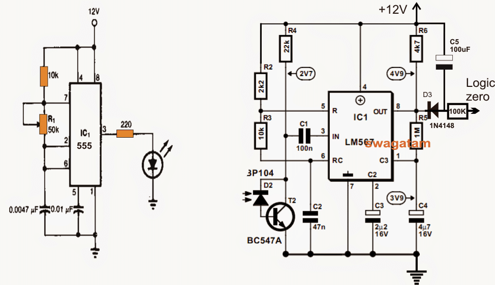
The first circuit utilizes a LM567 phase locked loop frequency detector chip to form the receiver circuit.
R2/R3/C2 fix the latching frequency for the IC such that the circuit responds and creates a zero logic output on detection of this frequency at its input pin3 via the photodiode.
The photdiode is triggered by a 555 based astable circuit shown at the left of the diagrams. The 555 circuit also employs a photo diode for transmitting the frequency over the receiving LM567 photo diode device.
The 555 transmitter must be tuned exactly to the frequency which is set with R2/R3/C2 in the LM567 circuit. Anything else is simply ignored by the Rx circuit.
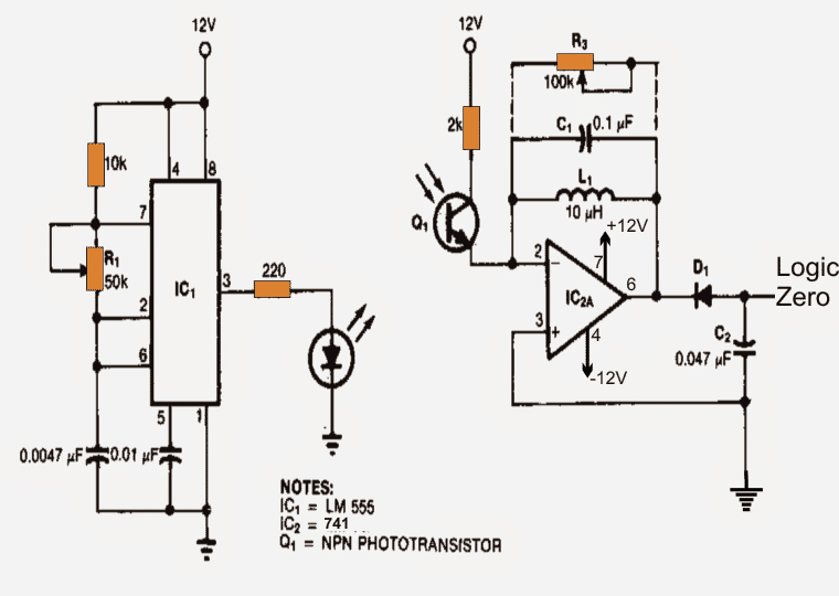
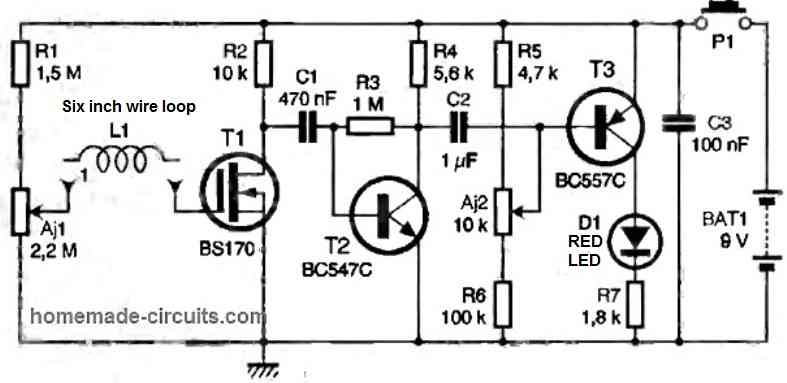
In the second tuned infrared detector circuit, an LC tuned opamp is employed for receiving an responding to the uniquely tuned transmitter frequency.
L1/C1 Feedback Loop
The L1/C1 feedback loop positioned across the opamp output input pinouts decides the latching resonant frequency on which it may be intended to latch on.
L1/C1 may be appropriately tweaked for achieving other unique tuned frequencies for executing the locking actions.
Here too a 555 astable is used as the IR transmitter for triggering the opamp Rx circuit.
On detecting a matching frequency from the 555 Tx, the opamp responds and creates a low logic at its output pin which may further integrated to an external device for the specified operations.
The above circuit can be appropriately used for the proposed train ID detection, and 8 such Rx units may be laid down the tracks, and the 555 Tx units on each of the trains, such that the uniquely selected number of trains with the unique Txs are detected by the Rx receivers and the corresponding low logic info is sent to the computer for informing the user regarding their presence.

Questions & Answers
Hi, both the designs are tuned circuits and will respond only to the specific frequency, so sunlight or any ambient light cannot have any effect on their outcomes…
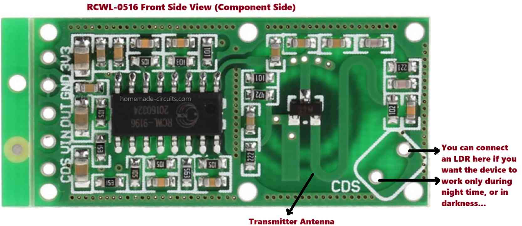
HI, I am thinking of sensitivity to transmission signal when ambiant light or sun shine on the sensor (BP104). In that case, is the signal transmitted correctly? (sunlight is considered as a disturbance)
Thank you
Alain
HI, I am thinking of sensitivity to transmission signal when ambiant light or sun shine on the sensor (BP104). In that case, is the signal transmitted correctly? (sunlight is considered as a disturbance)
Thank you
Alain
Hi, Please explain your concept, because I could not understand your thoughts regarding using sunlight with the first circuit.