Is your power amplifier fuse blowing during power switch ON? It could be happening due to the initial high current drawn by the loudspeakers, when power is switched ON.
The simple amplifier fuse protection circuits presented here can be effectively used for solving the issue.
The problem is commonly seen in high power amplifiers, where the loudspeakers have low resistance specs, or in power amplifiers which have many high power loudspeakers connected in parallel.
Why Amplifier Fuses Blow
In high power amplifiers, when power is switched ON, the various stages inside the circuit board take a few milliseconds to stabilize. However, before the circuit stages are able to stabilize, the MOSFETs are forced to conduct instantaneously due to the switch ON voltage spike, allowing the full input DC to pass though the connected loudspeakers. The loudspeakers being low in resistance create a momentary short circuit kind of situation causing heavy load on the fuses, until they blow of.
The situation is undesirable not only for the amplifier, but it may be also a threat to the loudspeakers, which may eventually burn due to repetitive high current switching, during every power switch ON.
How to Prevent Amplifier Fuse from Blowing
The idea is actually quite simple. To prevent the amplifier fuse from blowing we simply need to ensure that the amplifier input power is applied with a soft-start AC input.
To implement this a small delay ON timer can be employed.
Here's a design that was published a long time ago in the elektor electronics magazine, and still looks very handy for solving the blowing fuse problem in power amplifiers.
How the Circuit Works
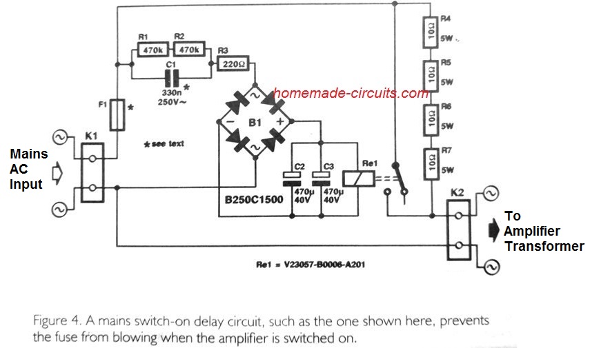
The above shown circuit is basically a delay ON relay circuit which initially keeps the amplifier transformer or the SMPS disconnected from the mains input. Instead of a direct initial connection, the circuit utilizes a few low value resistances to introduce a low current mains input to the amplifier power supply.
The R4--R7 resistances restrict the loudspeakers from drawing heavy initial current from the power supply, while allowing the amplifier circuitry to stabilize normally.
After a small delay, which could be around a second, the relay clicks and connects the mains input directly with the amplifier power supply. At this point, the speakers are unable to draw heavy current because the circuit is already stabilized, and it effectively controls the current to the speaker at the specified safe limits.
A Better Protection Circuit
Although the above circuit may look quite competent in solving the blowing fuse issue in power amplifiers, it doesn't appear to be the most efficient one.
It's because the circuit involves direct contact with mains AC input, and the resistances initially might dissipate some amount of power. This may not be much of an issues but it looks unnecessary because the same design can be implemented through an easier version, as indicated below:
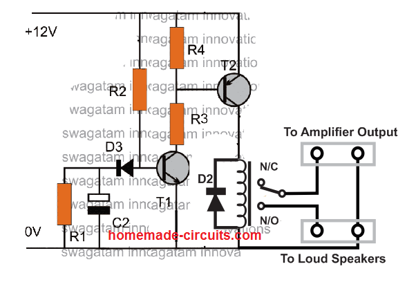
This is also a delay relay ON timer circuit but it works with a DC input derived from the amplifier SMPS or power supply.
When the amplifier is switched ON, the delay timer is also switched ON from the amplifier's supply. However, being a delay ON timer, the relay does not respond immediately rather waits for sometime depending on the values of R1, R2, C2. Once the set time elapses, the relay activates and connects the amplifier output with the loudspeakers.
The slight delay in switching allows the amplifier circuit to settle down adequately, ans switch ON the loudspeaker safely, thus preventing the fuses from sudden over current.
Parts List
- R1 = 100K
- R2 = 100K
- R3, R4 = 10K
- D2, D3 = 1N4007
- C2 = 100uF/25V
- T1 = BC547
- T2 = BC557
- Relay = 12 V relay, 10 amps.
Over to You
The protection circuits presented above provide an easy solution to blowing fuse problems in amplifiers. If you have any related queries or a better alternative than these, please let us know through comments below, we'll be happy to update the info in the article.


Comments
Hi Dear Swagatam;
I test my 48 inches led TV (230V 160W) with a serial bulb. At the test beginning the bulb blinks 5 times in every one second and then it blinks 3 times in every 100 mili seconds but this period is not regular after the initial period then for instant I see 1 time long blink and then 10 times short blinks.
Also I would like to ask that is it possible to test this device by using serial 15 mF capacitor?
Hi Suat,
it is difficult to judge why the bulb blinks that way.
Using series capacitor maybe a good idea but make sure to use a series resistor also to limit the initial surge current.
Thanks Swagatam I know it is hard to judge however I am grateful for your responce. Meanwhile I replaced the 15W bulb instead of the 100W bulb now it is regular and it blinks in every second. Also I am not sure about how to calculate the initial surge and the resistor value however I am sure that the surge current is less than 2A.
Hi Suat,
For suppressing surge current, you can simply add a 120 ohm 2 watt resistor in series with the capacitor and check the response. By the way, a 15uF capacitor itself will not allow over 1 amp current, so I think the resistor may not be required.
Swagatam, I have used serial 14uF C and the result is:
There are about 20V serial capacitor voltage and the main capacitors of the tv power board keep about 390 V (too high).
Suat, sorry, I could not understand your statement?
Can we continue the discussion under the following post, which looks more relevant to our discussion topic…
https://www.homemade-circuits.com/0-300v-variable-voltage-current/
Please let me know.
Hi Swagatam,
I only poked into your homepage but I found it very useful and informative, Congratulations! Please take as an intent of improvement what I’m to add now.
I believe the high current transient is hardly caused by the low impedance loudspeaker system. The fuses do not blow off anytime else, just at the turn-on, although the same speakers remain present all the time.
Depending on the phase situation of the power voltage, an amount of flux remains in the iron core of the power transformer at the turn-off. If the turn-off happens at zero crossing, it is negligible, but if it happens at the peak it must be taken into notice. Should the next turn-on happen at a moment when the line voltage is at the same angle and maximum amplitude, the excitation adds to the remanent flux and results in a magnetic saturation of the transformer core, consequently in a high current peak which can blow the fuse off. Small transformers have a considerable resistivity of their primary winding, so they save the fuse from blowing.
The first circuit (of Elektor journal) prevents the blow-off by exciting the transformer initially at low power, but the second has another aim. That is very useful in eliminating the pop of the speakers at the turn-on, caused by the initial transients – as you described. However, I don’t believe cross-connection of power MOSFETs ever happens in a well-designed audio amp.
Very best regards, Laszlo
Thank you so much Laszlo,
I truly appreciate your valuable information regarding the subject. I hope the readers will find it very useful.
Your website is very interesting I have so far tried one circuit with ice 4047 and mosfet transistor irf 3205 worked well , I have one question how to increase power out put
Glad you liked the website! To increase power, you will have to upgrade the mosfets, the transformer and battery to higher wattage levels appropriately.
How about a short circuit protection for amplifier’s output
It has been discussed here:
https://www.homemade-circuits.com/make-this-amplifier-shortoverload/