The precise battery capacity tester circuit explained in the following article can be used for testing the maximum backup capacity of any rechargeable battery in real time.
By Timothy John
Basic concept
The circuit works by practically discharging a fully charged battery under test through constant current, until its voltage reaches the deep discharge value.
At this point the circuit automatically cuts off the battery from the supply, while a connected quartz clock provides the elapsed time for which the battery had been providing the backup. This elapsed time on the clock informs the user regarding the precise capacity of the battery with respect to the set discharge current.
Now I have explained the detailed working of the proposed battery capacity etster circuit with the help of the following points:
Main Stages of the Circuit
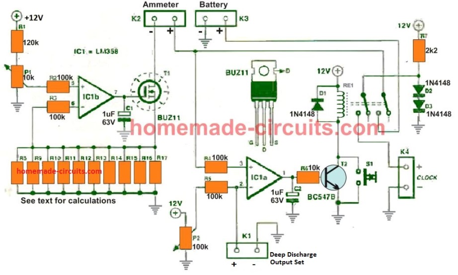
Referring to the above schematic of the battery backup time tester, the design can be divided into 3 stages:
- Constant Current Discharge Stage using IC1b
- Deep Discharge Cut off Stage using IC1a
- External 1.5 V Quartz Clock Supply Cut-OFF
A single dual op amp IC LM358 is used for implementing both, the constant current discharging and the deep discharge cut off process.
Both the op amps from the IC are configured as compartaors.
The comparator op amp IC1b works like a precise constant current discharge controller for the battery.
How the Constant Current Battery Discharge Works
The dummy discharge load in the form of resistors R8 to R17 is connected between the MOSFET source terminal and the ground line.
Depending on the preferred discharge current, an equivalent voltage drop is generated across these parallel resistor bank.
This voltage drop is noted, and the exact same potential is adjusted on the non-inverting input of the IC1b op amp, through the preset P1.
Now as long as the voltage drop across the resistors is below this set value, the op amp output continues to remain high, and the MOSFET stays switched ON, discharging the battery at the preferred constant current rate.
However, if suppose the current tends to increase due to some reason, the voltage drop across the resistor bank also increases causing the potential at the inverting pin2 of IC1b to go over the non-inverting pin3. This instantly flips the output of the op amp to 0V turning OFF the MOSFET.
When the MOSFET is turned OFF, the voltage across the resistor also drops instantaneously, and the op amp turns ON the MOSFET again, and this ON/OFF cycle continues at a rapid rate, ensuring that the constant current discharge is perfectly maintained at the predetermined level.
How to Calculate the Constant Current Resistors
The parallel resistor bank connected at the source terminal of the MOSFET T1 determines the constant current discharge load for the battery.
This imitates the actual load and discharge rate which the battery may be subjected to during its regular working.
If a lead acid battery is used, then we know that its ideal discharge rate should be 10% of its Ah value. Assuming we have a 50 Ah battery, then the discharge rate should be 5 amps. The battery could be discharged at higher rates also, but that might seriously affect the battery life negatively, and therefore a 5 amp becomes the ideal preference.
Now, for a 5 amp current, we must set the resistor value such that it develops may be around 0.5 V across itself in response to the 5 amp current.
This can be quickly evaluated through Ohms law:
R = V/I = 0.5 / 5 = 0.1 Ohms
Since there are 10 resistors in parallel, the value for each resistor becomes 0.1 x 10 = 1 Ohm.
Wattage can be calculated as 0.5 x 5 = 2. 5 watts
Since 10 resistors are in parallel, the wattage of each resistor can be = 2.5 / 10 = 0.25 watts or simply 1/4 watt. However, to ensure a precise working, the wattage may be increased to 1/2 watt for each resistor.
How to Setup the Deep-Discharge Cut-off
The deep discharge cut off which decides the lowest voltage threshold for the battery backup is handled by the op amp IC1a.
It can be set in the following manner:
Let's assume the lowest discharge level for a 12 V lead acid battery to be 10 V. The preset P2 is set such that the voltage across the K1 connector produces a precise 10 V.
This means that inverting pin2 of the op amp is now set at a precise 10 V refernce.
Now, at the beginning, the battery voltage will be above this 10 V level, causing the pin3 non-inverting input pin to be higher than the pin2. Due to this the output of the IC1a will be high, allowing the relay to be switched ON.
This would in turn allow the battery volatge to reach to the MOSFET for the discharging process.
Finally, when the battery is discharged below the 10 V mark, pin3 potential of IC1a becomes higher than pin2, causing its output to become zero and the relay is switched OFF. The battery is cut off and stopped from further discharging.
How to Measure the Elapsed Backup Time
To get a visual measurement of the battery capacity in terms of time taken for the battery to reach the full discharge level, it is essential to have a time indicator which would show the elapsed time from the start, until the battery has reached the deep discharge level.
This can be simply implemented by connecting any ordinary quartz wall clock with its 1.5 V battery removed.
First, the 1.5 V battery from the clock is removed, then the battery terminals are connected to the K4 connector points, with correct polarity.
Next, the clock is adjuated to 12 0 clock.
Now, when the circuit is initiated, the second pair of the relay contacts connects the 1.5 V DC from the junction of R7/D2 to the clock.
This powers the quartz clock so that it can show the elapsed time of the battery discharging process.
Finally, when the battery is deep discharged, relay toggles and disconnects the power to the clock. The time on the clock freezes and records the precise battery capacity, or the real backup time of the battery.
Testing Procedure
Once the assembly of the battery capacity tester of finished, you will need to connect the following accessories to the various connectors from K1 to K4.
K1 should be connected with a voltmeter for setting the deep discharge voltage level through P2 adjustment.
K2 can be connected with an ammeter to check the constant current discharging of the battery, although this is optional. If an ammeter is not used at K2, make sure to add a wire link across the K2 points.
The battery under test should be connected across K3 with correct polarity.
Lastly, a quartz clock's battery terminals should be connected across K4 as explained in the previous section.
Once the above items are appropriately integrated, and the presets P1/P2 setup as per the previous explanation, the switch S1 may be pressed for initializing the battery capacity testing process.
If an ammeter is connected, it will immediately start showing the precise constant current discharging as set by the MOSFET source resistors, and the quartz clock will begin recording the elapsed time of the battery.
Audible Battery Tester
This simple audible battery tester circuit checks the condition of all types batteries from 1.5 V to 12 V. A standard oscillator is found in this circuit whose output frequency is fairly independent of the supply voltage but differs a lot with variations in supply impedance. So, with the individual electronic components shown, a new battery or cell will deliver a note of around 500 Hz.
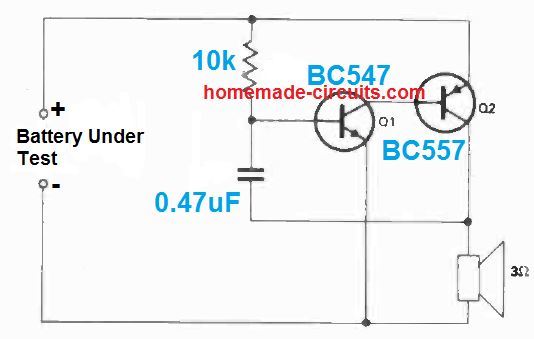
When an exhausted cell is placed, a note around 1 kHz is provided. The device has been examined with battery voltages between 1.5 V and 14 V, utilizing a BC547 as Q1 and an BC557 as Q2.
You can also use the battery in the reverse polarity and still make the circuit work without any problems.


Comments
Hi Mr. Swagatam;
Ref. to above audible tester circuit.
I have in hand of c32825, c548b, bc212b(b or 8) and s8550 instead of the Q2. Is it possible to use one of them?
Hi Suat,
you can use any small signal PNP transistor for Q2 in the last design.
BC548 is NPN so it won’t work.
Make sure the BJT you are using is a PNP….
Thanks Swagatam. I see Q2 should be PNP but please advise it should be amplifier or small signal type or both type are available to use on the circuit?
Hi Suat, all BJTs are amplifiers. In the last design, a small signal PNP BJT is recommended for Q2, so your 8550 will work good.
Hi,
I am basically Mechanical engineer want to produce Lead Acid/ Lithium Battery Charger/Tester & 400VA Sine Wave Inverter PCB.
Please help me to design PCB & Manufacturing advise.
This is purely for Export purpose.
Regards,
Hi, learning PCB designing is a long process which will require softwares and many practical experiments. It cannot be expained in comments.
Hii This is general question, How much we have to discharge 1.2 v Ni mh cells. I mean what is the instructions for discharging cycle. Do we have to full discharge and then charge?
Hi, I think it should not be below 0.9 V, and should be fully discharged before recharging, since Nickel based batts do have a memory effect.