An emergency lamp using SMD LEDs is able to generate illuminations with extreme brightness due to the high efficiency of the SMD type LEDs. Moreover, SMD LEDs also ensure the unit will be very compact and lightweight.
The following post explains a simple circuit diagram of an automatic emergency lamp using 36 nos. SMD LEDs. The circuit has been presented in response to the following request sent by Mr.Ali Adnan.
Circuit Request for SMD Emergency Lamp
I've 36 SMD LEDs(Side View Type), I Extracted them from my Broken Laptop's LED LCD screen. I tested them with multimeter and found all LEDs in working condition.
Now I want to make some useful from them like an emergency LED lite. I'll remove all 36 LEDs from strip and mount them on a PCB (will be Tough JoB Mounting SMD's) once you will design a circuit for me to drive them.
I don't know much about SMD LEDs so that's why I am bothering you. I googled for data sheet for that type of LEDs and I think I found right data sheet for this LED, please also compare the pictures of LEDs and data sheet.
I am attaching actual pictures of LEDs that I have and also attaching data sheet, please check and help me with a simple circuit with simple parts. and just for information I've not found the IC ZXSC310 (that you used in your 1 watt LED circuit) here in Lahore Pakistan 🙁 and I am too sad for this.
Waiting for your Reply.
Best Regards,
Ali Adnan Khan
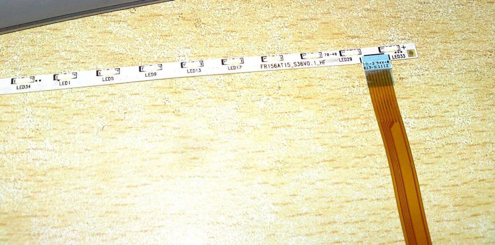
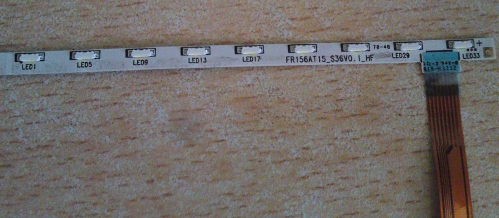
"Hi Bro,
What kind of emergency light do you want to make? Automatic AC/Dc operated or just direct on battery?
The datasheet and the pics are OK.
Best Regards,
Swagatam"
"Hi, thanks for your reply bro. Automatic AC/DC operated with battery backup."
OK, here's an automatic ac/dc emergency light circuit using the proposed 36 SMD LED lights which is easy to build, cheap and yet reliable.
CAUTION - THE CIRCUIT IS NOT ISOLATED FROM AC MAINS, UTMOST CARE MUST BE OBSERVED WHILE TESTING THIS CIRCUIT IN UNCOVERED POSITION.
ALTERNATIVELY YOU MAY INCORPORATE A 12V, 500MA DC ADAPTER ACROSS THE ZENER DIODE INSTEAD OF THE SHOWN TRANSFORMERLESS POWER SUPPLY FOR AVOIDING THE ABOVE CAUTION.
The Design of a an Automatic SMD based emergency lamp is shown below, as per the above request specification:
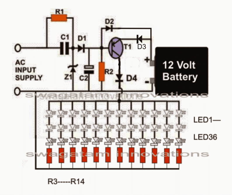
Parts List
All resistors are 1/4 watt, 5%,
- R1 = 1M
- R2 = 1K,
- R3---R14 = 56 Ohms
- C1 = 2uF/400V PP Capacitor
- C2 = 100uF/ 25V
- D1, D2 = 1N4007,
- D3, D4 = 1N5402
- T1 = TIP127
- Z1 = 15V 1 watt zener diode
- Battery = 12V/2AH
- LEDs = SMD, 3V white, 20 mA


Questions & Answers
Hi sir, I would like to know about the emergency light with more brightness. Please send me a simple diagram with capacitors value,
Hi Shahnawaz, you can try the concept which is explained in the above article. It will give you maximum brightness. But you will require a Li-Ion battery for the high brightness and long back ups.
Automatic ac led lamp to operate when ac fail and it will go to dc battery circuit digram
hello sir,
sir i want to use two 6v 1aH BATTERIES in series with the circuit,so what modification would be required.
Siddharth, 6V 1ah is OK for the circuit, but it won't support 84 LEDs, it would get discharged very quickly.
for IR control you can try the following method
https://www.homemade-circuits.com/2012/02/how-to-make-simple-infra-red-remote.html
sir the batteries i am using are 6V1aH li-on battery, Will that suffice ??? also the led smd i have with me has 84 units in it so any modification would be required???
Also i want to add a feature of IR control, so what should i do??
Hi Siddarth, you can use the same circuit as given, no modifications would be required,
sir,
i want to use two 6v 1AH batteries in series. So what modifications would be required.
Hii.i want 220ac to 22volts dc 2.5amps circuite with out transformer.
sir how much time does take for full charge??
70mA 12V
This circuit how many output voltage & amps
I used 12v realy this circuit out voltage & amps please tell me sir
use a 12V relay with 300 ohm or 400 ohm coil resistance
I used ac supply working time LED OFF MODE I used relay what volt realy used sir please tell me sir
relay coil voltage should match the zener voltage….
Iam add in 12v 2 amps Battery Two Battery parller
ok will do.
I want one 12v 4.5amps battery any modifications circuit diagram please tell me sir
no modifications would be required
Thanks you sir
How to converted battery zener series
Or parller connect please tell me sir
connect the black line of the zener with the battery (+) terminal and the other side of the zener with the battery (-) side…use a 14V 1 watt zener
How to Stop over charging this circuit
connect a 14V/1watt zener diode right across the battery terminals, this will do the job for you.
I used 12v 4.5amps this circuit
I used 6v 4.5 amps this circuit diagram
you can use the second circuit from the following article:
https://www.homemade-circuits.com/2014/06/flashing-led-battery-status-indicator.html
use only a single 5mm red LED with the last transistor
How to fixed charging indicate led ?
I used 2 12v 2 amps battery parallel how to modify circuit?
This circuit support 6v 4.5 amps battery used?
Connect a resistor in series with D2, and connect an LED parallel to this resistor, as long as the battery charges this LED will glow and will gradually shut-off as the battery reaches full charge.
the resistor value could be anywhere between 2 and 10 ohm….you will need to experiment the right value
if possible connect a 47 ohm resistor in series with one of the LED lead for safeguarding it
How to fixed charging LED please send me sir
I did not understand?
How converted in to 12v /7AH battery used this circuit please tell me sir
this circuit cannot be used for charging a 12V/7AH battery.
I am having transformer 12v 2Amps. i replaced it, the whole night it took, but Battery backup didnt increase.. The system works (when the AC is on, DC off). the transformer is also so Hot….
your battery could be internally damaged….put an ammeter in series with the battery and check how much current it is taking in…if it shows zero will indicate a faulty battery.
the circuit works well but it charges slowly in my 12v 5amps bike battery. how to charge fast pls help me
for quicker charging you will need to remove the transformerless supply stage consisting C1, R1, Z1, and replace it with a 12V 1amp AC/DC adapter input
i am having 12v 5amp Bike battery, it has 8.5v. it charges slowly… how to recharge fast
Please help me
Sir
Your circuit ideas are valuable and useful.So many people are taking advantage of it
You are rendering a great service to the world.
Best regards
Best regards
thank you Jithin!!
Sir can you provide me any schematic or give any idea about the 2 watt led blinker with strobe light.(i will use two 1 watt led in parallel)..
The circuit should work in this manner…When we press the button the led will glow continuously and the second press will make the led to Blink. and finally the third press will turn off the led.
I have seen similar feature in Cree led torch ..
Sir please guide me…
Syed you can try the circuit that's shown in the following link with a few external modifications:
https://www.homemade-circuits.com/2013/08/single-push-10-step-selector-switch.html
Remove all the relays and connect the LEDs at the collector of the pin2 and pin4 transistors, use TIP122 for the transistors.
Connect pin7 with pin15 through a 10k resistor instead of pin10 and remove the transistor stage at pin7 because we don't need it.
Now make a 555 PWM circuit and integrate its pin3 VIA a DIODE 1N4007 to the base of pin4 transistor…diode anode to base, cathode to pin3 of 555.
That's it your circuit is ready.
we haven't use a bridge rectifier sir. may i know what diodes to use? thanks a lot sir.
Kim, you can use 1N4007 diode for making the bridge or simply connect the transformer wires directly across the anode of D1 and ground in the circuit that's shown in the above article.
remove C1, R1,Z1 these are not required.
thanks for the help sir. we will try changing it and tell you the results.
thank you very much sir.
its like the AC is giving it power because you can notice the light flickering. im sorry sir but im new to transistors but I know that it can act as a switch.
I can see that you changed the position of D3. we haven't tried that yet.
I also measured the voltage across the base and emitter. when the AC is off, it has voltage and when it is on, the voltage is zero. but I connected it to D3 in the old diagram where it is directed to the LEDs. Is it wrong?
thanks Kim,
yes I have made a slight change by putting D3 at the emitter of the transistor, just to make the results more accurate.
By the way did you use a bridge rectifier for rectifying the transformer voltage to DC before applying to the circuit?? otherwise the LEDs won't shut off correctly.
You can try changing the position of D3 as shown in the new diagram and check the results.
we are using an 18 volt transformer with 750ma
we love your work a lot and we think that it is amazing. but sir we are having a problem now. thank you very much for your help.
with 18V at the base of the transistor it should completely cut of….
the transistor may not be OK, or some other issue could be there.
Good day sir,
May I ask if it is okey to put an 18V/750mA transformer instead of a transformer-less AC supply? and change D3-D4 to 1N4001 or 1N5401?
Also, whenever I connect the AC supply, the LED are still giving light. What could be the possible problem?
Your kind response wuold be greatly apprecieted. Thanks.
measure the voltage across the base and emitter of the transistor with transformer supply ON, and also everything else connected.
It should be around 0V to make the leds shutof.
if not, check and make sure the rectified voltage from the transformer is higher than the battery voltage….
if still it doesn't work, your transistor could be faulty.
or you can opt for a NPN transistor design circuit as shown at the extreme end of this article:
https://www.homemade-circuits.com/2011/12/how-to-make-efficient-led-emergency.html
we already tried to increase to R2 to 10K but the transistor heats up and the leds wont light. the leds only light up when we use 1k resistor on R2.
is it okey to remove the transformer?
thank you very much sir 🙂
Kim, increase the value of R2 to 10K, or 22K, or 33k until the LED shuts off completely while mains is present.
please remember that the base voltage (or the supply voltage from the transformer) to the transistor must be slightly higher than the battery voltage otherwise the LEDs will keep glowing even if R2 is increased to any level.
the leds dont shut down but it dims its light sir.
yes sir. we are already using those diodes on our circuit. On a tip127 transistor, is the base on the left most pin, collector on the middle pin and lastly emitter on the last pin?
and we are using two 6volt batteries in series with 4aH each. whenever we connect the AC source, the led's just dims.
and lastly, we are using a ready made led sheets with 3 SMD leds per sheet that is intended for cars. does these have to do with our problem?
please sir, you've been a great help. thank you very much.
Good day Kim,
yes a transformer power supply could also be used
use 1N4007 for D1,D2, 1N5401 for D3/D4.
if LEds are not shutting off at mains switch ON, indicates a faulty transistor or incorrectly connected transistor.
Sir iam using 12v 5amp bike battery with 40leds. Brightness is low. If I directly connect leds to battery brightness is good. I used 6.8ohms resistors R3-14. Please tel how can I modify circuit to get more brightness. Thanks.
dhanusu, please provide the wattage of the LEDs so that i can calculate it correctly.
If I Give 12v supply through transformer 15v zener is needed in circuit or shall I remove zener. Pls tel.
you can remove the zener.
need a ckt to drive Chinese led torch (4 led in parallel with only one limiting resistor to the bank, operate on 4 v rechargeable battery) from a 12 v bike battery without any power loss. thanks
use a 7805 IC in between 4V batt and 12V batt.
hello dear sir,
i want to make an automatic AC/DC led light switch with transformer less supply.
when AC supply on the led,s should be on and when AC fails then it should be shift to battery back up .
i want to run only 5 LED,s of 1 watt each.
i shall be very thankfull to you for this.
best regards.
Sameer Ali
Hello Sameer,
you can try this circuit:
https://www.homemade-circuits.com/2011/12/how-to-make-efficient-led-emergency.html
use TIP127 instead of the shown transistor.
you will need a transformer power supply for driving 5 watt leds as shown in the first figure.
yes…
You can try the following circuit….you may remove the three collector diodes, they won't be required:
4.bp.blogspot.com/-ZCs8Ry6l_nE/T12Li7DXPDI/AAAAAAAAA64/8JHMz9lAeUw/s1600/led%20emergency%20light%20circuit%20diagram.png
The LED resistors may be selected as 100 ohms.
sir i want to know that why u used a R2 in parallel how supply voltage offs and blink led on battery through R2
it transistor can change with another model?