Named after its creator, the theremin originated in the Soviet Union in the beginning of 1920's. This comprised of a container installed with a couple of antennas. It did not have any keyboard to play, no strings like in guitars. Rather, the theremin made use of human body capacitance to manipulate the volume and the pitch and of the output musical signal. The operator just had to wave his or her arms close to the antennas to generate a correspondingly varying musical tone!
Contributed by Ragini Sharma
Early Applications
The most significant application of the theremin has been in an uncounted variety of low budget horror movies. The spooky strooling noises heard in those movies during many actions were actually created from a theremin device.
Likewise, They have also been used in many pop and rock music concerts. Although the the first theremin made use of a couple of antennas and a variety of pipes and tuned circuits, replacing them with modern integrated circuits makes the work drastically simpler.
How much will it Cost?
In this post, we'll learn the development of a straightforward theremin with components that may be worth less than $5. Electronic enthusiasts having a junkbox full of components might manage to get the job done for possibly a lower cost.
The theremin is effortlessly put together and applied, even by individuals with no musical qualifications. On top of that, the theremin could be loads of enjoyment, particularly at Halloween celebrations!
In this circuit, the pipes and LC circuits are actually changed with a couple of low-cost and readily available IC's, to generate the proposed Digital Theremin.
Understanding the Block Diagram
A block diagram of the circuit can be found in the following in Fig. 1.
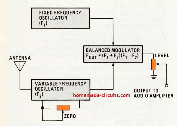
The Theremin works with a set of two high frequency oscillators for functioning. One of these oscillators funtions with a constant frequency, while the other is variable through the body capacitance of the operator.
The frequency generated from the two oscillators are combined through an exclusive circuit called the balanced modulator.
The balanced modulator attenuates the initial signals and generates a complicated transmission which includes the sum and difference frequencies in the two inputs.
When one particular oscillator is performing at 100 kHz and the second one at 101 kHz, we will get an output constituting a pair of frequencies at 201 kHz and 1 kHz.
Because the higher range of human ability to hear is restricted to 20 kHz or so at the most, only the 1 kHz difference frequency will be hearable due to the influence of the balanced modulator connected before an audio amplifier.
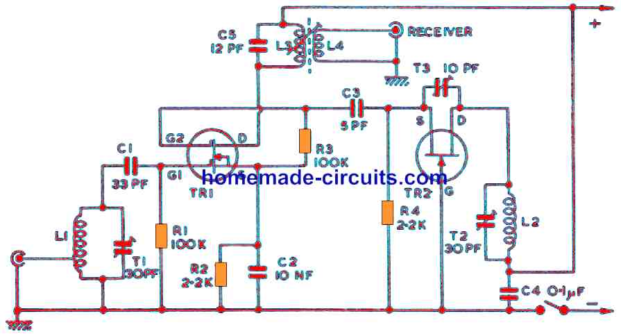
How the Circuit Works
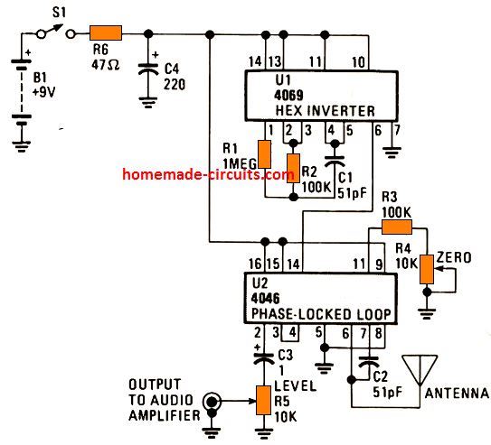
The schematic picture for our Digital Theremin is demonstrated in the above figure.
U1 could be either a CD4069 or 74C04 hex inverter, it is used like a constant frequency oscillator fixed around 100 kHz.
IC U2 includes the variable frequency oscillator and balanced modulator to accomplish the remaining portion of the circuit.
The CD4046 is a phase-locked-loop configuration and had been initially created for frequency multiplier type applications. However, its components fulfills our requirements flawlessly.
R3, R4. and C2 establish the center frequency of the built in oscillator chip. The antenna creates a parallel capacitance together with C2, that enables the frequency to get changed many kilohertz when a human hand approaches the antenna.
The ZERO control resitor implemented by R4, makes it possible for the variable oscillator to be fixed at the identical frequency equal to the fixed oscillator.
If the difference frequency is under 15 Hz, it is under the lower frequency threshold of our hearing range.
By tweaking the two oscillators for the identical frequency, the Theremin stays muted until the operator or the performer moves his or her hand close to the antenna.
The frequencies created by the two oscillators are combined by an exclusive OR gate within the IC 4046.
This gate works like a digital balanced modulator, that creates the sum and difference frequencies as discussed previously. The OR gate output is subsequently AC coupled through C3 with LEVEL control resistor R5 and an output jack for a quick integration with an external audio amplifier. A 9 V PP3 battery can be used for powering the circuit.
PCB Designs
It is a simple circuit and could be assembled with a 2x2-in PCB . A track layout for the printed circuit board of Theremin as displayed in figure below:
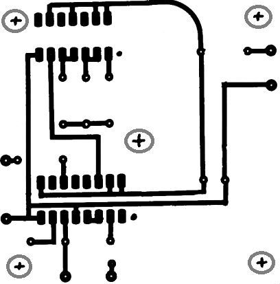
One important aspect is that the Theremin must be mounted into a metal case only, since the metal forms a shield that greatly eliminates the potential for the oscillators to change in frequency.
Having the metal case enables the theremin far simpler to calibrate.
C1 and C2 both need to be silver mica capacitors for optimal outcomes, ideally with a tolerance of ± 5 per cent.
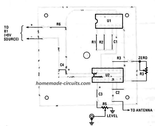
Since both chips are CMOS it is highly recommended to incorporate IC sockets. Apart from that, the board 's layout and assembly is uncritical.
Once the project is finished, we have to work with installing the antenna and attaching it to the board.
Because the antenna is protected with a fine coating of chrome, it isn't possible to solder a wire effectively to the antenna on its own. Just connect a small piece of wire to one of the washers and attach it to a 2-56 machine screw and bolt antenna (see Figure 5).
Calibration and Testing
Upon completion of assembly, closely check the Theremin for defects in the interconnects, weak solder joints and other possible issues. If everything looks perfect, connect the Theremin with a cord up to an audio amplifier, add a battery to the device, and switch it ON.
Slowly and gradually increase the volume with the LEVEL control. If everything works correctly, you might be suceessful in hearing a high-pitched squeal. Now, waving your hand close to the antenna should cause the pitch of the sound to boost. Try increasing the antenna length to its full capacity and fine-tune the ZERO control knob to identify a sweet spot where a dead zone or null-spot is noticed until of course your hand is brought near the antenna.
Troubleshooting the Circuit
In case the squeal fails to arrive at any tuned spot, try making the antenna shorter by a few inches and give it a try again.
Once the setting up is implemented accurately, the Theremin should keep muted until the operator waves his or her hands within a few inches from the antenna.
You may come across numerous aspects influencing the human body capacitance, and all of these could affect the Theremin's efficiency level.
Aspects such as the antenna length, air moisture, the size, and operator's costume, and the shoe sole resistance to ground could all influence to warrant an alteration in the ZERO control adjustments.
Through some practice, the ZERO control could be appropriately set in a matter of seconds.
Lastly, the Theremin must be offered a few minutes to become stable, on account of temperature variations, soon after the supply voltage is initially switched on.
When the Theremin is energized and right away zeroed, it will likely cause the tuning to drift and demand a re-calibration repeatedly.
The most effective remedy would be to switch the power on using the LEVEL control completely down, and provide the Theremin several minutes or so to warm up before calibrating the ZERO control.
Conclusion
The Theremin works naturally and with special audio effects.
A volume pedal enables you to bring dynamics and introduce fadeouts, and nearly any of the ground device for guitarists or synthesizers may alter a few element of the sound quality.
The ethereal sound of the Theremin performs wonderfully using echo and delay enhancements.
Regardless of whether the Theremin is employed like a special effect generator for rock groups or cinema organizations, or simply to enrich your future Halloween celebration, you will discover that this gadget can provide you with lots of unconventional sound effects using a incredibly humble expenditure in terms of time or money.
Not only is the Theremin fascinating and informative, is actually great fun!
Parts list
C1,C2 - 51 pF, silver mica capacitor
C3 - 1 uF, 25-WVDC electrolytic capacitor
C4 - 220 uF, 25-WVDC electrolytic capacitor
R1 - 1 M, 1/4 -watt. 5% resistor
R2, R3 -100 k, 1/4 -watt, 5% resistor
R4 -10 k, linear potentiometer
R5 -10 k, audio potentiometer
R6 - 47-ohm, 1/4 -watt, 5% resistor
U1 - IC 4069 or IC 74C04 CMOS hex inverter/buffer, integrated circuit
U2 - IC 4046 phase-locked loop, integrated circuit
ADDITIONAL PARTS AND MATERIALS
Printed -circuit or perfboard materials, general-purpose replacement antenna aluminum case, IC sockets, 9-volt transistor -radio battery, 9 -volt -battery clip, wire, solder, hardware, etching solution (if needed), etc.
Theremin Circuit using TSL245
Our next design converts light into sound using an IC TSL245 and a phototransistor, creating a straightforward light-operated theremin. Theremin is a remarkable musical instrument that can be operated without touching or making contact. It can be tuned just by sweeping your palm close to the circuit. In this way you may alter the output's pitch and loudness.
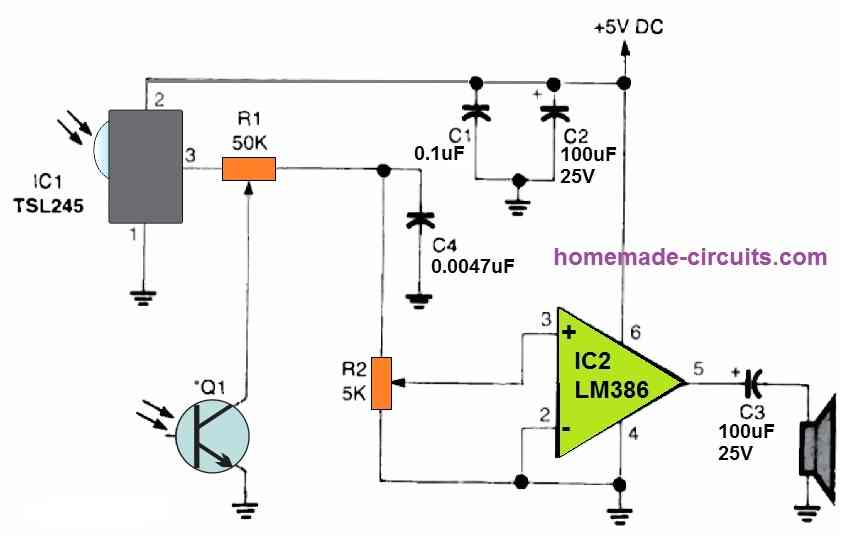
As shown in the diagram, a voltage-divider circuit and a phototransistor Q1 is linked between the input of IC2 and the output of IC1.
The tone output level of Q1 is determined by the surrounding light level. This minimum light level determines the maximum tone output when Q1 is darkened or blocked). The output level's volume is controlled by slight adjustments in IC1.
Use one hand to manipulate the volume and the second to adjust the tone while keeping Q1 and IC1 approximately ten inches apart.
To get the optimal loudness working range, tweak potentiometer R1. Put some IR screens (negative films) over the phototransistor if excessive light is reaching it. You may change the quantity of filters (negative films) to find the optimum high/low pitch functioning range. For the regulation of volume defined by IC1, a similar process could be necessary.

Questions & Answers
Thanks for an amazing and helpful site. I want to build the Theremin but am having trouble sourcing the Electrolytic capacitors – C4 220pf and C3 1nf. Are the values correct?
Thank you for your interest in this project, and sorry for the confusion, actually C3 is 1uF/25V and C4 is 220uF/25V which are mistakenly written as 220pF and 1pF. I will correct them soon.
can you design a theremin that could drive 10 leds, and include sound?
You can easily modify and use the above design to fulfill your requirements.
Greetings! I built the circuit (more than one actually) and it sounds very off like distorted and multi pitched. Not like any Theremin I have ever heard. What could cause something like this or is this normal for this design? I have tested the values on the capacitors especially the 51pf and they are all in spec.
i dont personally have much experience in using the hex inverter IC in the circuit but i do know many people have used them to make distortion, overdrive, and fuzz pedals. even a few big name pedal companies have released some. my guess is that its somehow overdriving the hex inverter. again im not sure what that entails because its something i was actually going to look into very soon but just havent gotten around to picking up any of the hex inverters yet.
and i think (if i recall correctly) that is the very same hex inverter chip that the majority if not all of the designs ive seen so far actually use also. but i could be totally wrong, as im not officially schooled in any of this. just kinda been self-teaching for a few years now.
Hi, the circuit was actually contributed by a external author, so I have no idea regarding its working performance or reliability.