This simple mains 220 V, 110 V AC voltage home protector circuit will protect all the mains operated appliances of your home from high and low voltage situations and also from sudden voltage surge.
The circuit can be used with 220 V AC inputs and also with 110 V AC inputs.
The circuit will basically provide the following two types of protection to all your home appliances:
- Protection against high and low mains voltages.
- Protection against sudden voltage switch ON surge whenever AC mains restores after a brief voltage failure.
This circuit performs incredibly well and is highly suitable for home appliances.
Circuit Description
With reference to the following diagram, the working of the proposed AC mains home protector circuit can be understood with the help of the following points:
Parts List
- All Resistors are 1/4 watt CFR 5%
- R1, R2, R4, R5 = 10k
- R3 = 4.7k
- R6 = 22k
- P1, P2 = 10k presets.
- Capacitors
- C1, C2 = 1000uF/25V Electrolytic Capacitors
- Semiconductors
- Diodes D1, D2, D3, D4, D7 = 1N4007
- Diodes D5, D6, D8 = 1N4148
- Zener Diodes Z1, Z2 = 4.7V, 400mW
- Transistors T1, T2 = BC547
- IC op amps A1, A2 = 1/2 IC LM324, or LM358 (pinouts will change accordingly)
- Transformer TR1 = 0-12V, 500mA
- Relay = 12V SPDT 30 amp
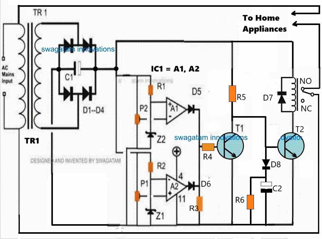
The two op amp comparators form the heart of the circuit which are configured as a window comparator for sensing the over and under voltage thresholds.
Window Comparator
A window comparator circuit is usually built using two op amps. One op amp is configured to sense the upper voltage limit threshold and the other op amp is configured to sense the lower voltage limit threshold.
Whenever the upper or the lower voltage limit thresholds are exceeded, the relevant op amp output goes high.
On the other hand as long as the voltage level stays within the safe limits, both the op amp outputs remains logic low or turned OFF.
In our home protector circuit, the upper op amp A1 is configured to sense the low voltage threshold, while the lower op amp is wired to sense the high voltage threshold.
For op amp A1, its non-inverting pin is clamped to a fixed voltage reference using a zener diode, while the inverting input is configured with a preset to sense the lower voltage threshold.
As long as the transformer DC (which is proportionate to the mains AC level) at the inverting input of A1 stays above the non-inverting pin's reference voltage, the output of A1 remains at 0V.
However, in an event when the input voltage at the inverting pin goes lower than the reference voltage at the non-inverting input, causes the output of A1 to go high.
Identically, but with an opposite function, op amp A2 utilizes a zener diode to establish a constant voltage reference at its inverting input pin, while the non-inverting input is configured with a preset to detect the high voltage threshold.
The output of A2 remains at 0V as long as the transformer DC, proportional to the mains AC level, at the non-inverting input stays below the reference voltage at the inverting input pin.
However, if the voltage at the non-inverting input rises higher than the reference voltage at the inverting input, it prompts A2's output to go high.
Thus, the two op amps makes sure that as long as the input voltage level stays within the preset "window" level, the outputs of both the op amps remains at 0V or logic low.
These voltage levels inside the comparator "window" signifies the safe limits at which our home appliances can work normally without any danger.
This safe limit, or conversely the upper and the lower unsafe cut-off limits can be appropriately adjusted and set using the P1 and P2 presets.
Transistor/Relay Switching
Now, while the mains AC voltage is within the safe limits, the outputs of the op amp remain at 0V, which keeps the transistor T1 switched OFF.
While T1 remains switched OFF, T2 remains switched ON causing the relay also to be in the switched ON position.
In this position the relay contacts are at the N/O position which allows the home AC supply to the appliances to be switched ON and working.
However, in an event when the input mains AC voltage tends to go higher or lower than the set threshold, the relevant op amp's output goes high. In either situation, T1 is switched ON.
As soon as T1 is switched ON, T2 base is grounded by T1.
This causes T2 to be switched OFF. When T2 switches OFF, it switches OFF the relay as well, causing its contacts to move towards its N/C position.
With the relay contacts shifted at N/C, the voltage supply is cut off for the home appliances, which safeguards them from the hazardous voltage situation.
Switch ON Surge Protection
The above functioning takes care of the high and low voltage correction and cut off, but what about the sudden voltage surge, during power failures and restorations?
The switch ON voltage surge is handled by the little delay ON timer configuration built using D8, C2, R6.
Whenever there is an input AC mains supply failure or interruption, C2 is fully discharged via R6.
Now, when the AC mains voltage returns, T2 and the relay are inhibited from switching ON instantly.
During this period, C2 slowly charges and keeps the base voltage of T2 below 0.6V causing it to be switched OFF, so that the relay and the home appliances also remain switched OFF.
As C2 charges slowly via R5, after some delay the voltage across C2 reaches above 0.6V which is enough to switch ON T2, relay and the appliances very softly.
This slight delayed switch ON after the mains has restored safeguards the home appliances completely from a possible hazardous switch ON voltage surge.
Calculating the Tripping Points
To setup the presets correctly we first need to confirm what levels of the DC voltages correspond to the 220V 120V AC side high and the low levels.
This can be actually quickly implemented using a variac, however since a variac may not be accessible to most of the users, we can try an alternative method through some calculations and practical testing.
Initially, keep the entire control circuit detached from the bridge rectifier.
Assuming your input AC supply is normal, switch ON the 220V or 120V to the transformer from the primary side and measure the corresponding DC output across the C1 or the bridge rectifier +/- ends.
Let's say you get a corresponding DC output of 16V. So this will be your DC equivalent of a normal 220V AC input.
Let's denote the high voltage DC tripping point as HV and the low voltage DC tripping point as LV.
We know that 220V AC corresponds to 16V DC from the above description. Let's assume the high voltage input at which the circuit is supposed to trip as 280V.
Therefore, the DC equivalent for this 280V AC high voltage can be calculated using the following cross-multiplication.
220/280 = 16/HV
HV = 20V
This 20V DC becomes the high voltage cut-off equivalent for the 280V AC side high voltage input.
Now, let's assume the low AC voltage cut off point to be 190V.
Similarly, as above, we can calculate the DC low voltage equivalent using the following cross-multiplication:
220/190 = 16/LV = 13.81V
LV = 14V
This 14V becomes the DC low voltage equivalent for the 190V AC side low voltage.
Now, since we have the high voltage and low voltage DC tripping points in hand, we can now quickly setup the presets P1, P2 through the following steps.
How to Setup
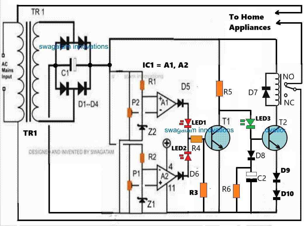
Please refer to the following modified diagram while setting up the circuit. I have improved the circuit design with a few modifications as indicated below:
I have added LED1, LED2, LED3 for indicating the various operating levels of the circuit.
LED1 (red) indicates a low voltage situation. LED2 (red) indicates a high voltage situation, LED3 (green) indicates a normal voltage situation.
I have changed the position of R3 (4.7k) to the base of T1, for improved T1 conduction.
I have added D9, D10 diodes (both 1N4148) at the emitter of T2 to enable improved Delay-ON switch ON feature of the circuit.
Take a variable DC power supply with a maximum range of 24V DC.
Disconnect the transformer stage from the circuit and hook up the variable power supply to the op amp circuit.
Keep R5 end disconnected from the positive supply.
In the circuit, P1 determines the high voltage cut-off point, and the P2 preset determines the low voltage cut-off point.
Initially, keep the P1 wiper arm of the preset fully towards ground. Keep the wiper arm of the P2 preset fully towards the positive supply side.
Adjust the power supply to around 16V and switch it ON, you might notice the following things.
You will find LED1, LED2, LED3 all turned OFF.
Now, adjust the variable power supply output to 20V, and carefully adjust the P1 preset until the LED2 just illuminates. To confirm the result try reducing the 20V to 19V, you should find the LED2 shutting off, this would confirm your high voltage cut-off point is fixed.
Now, reduce the variable power supply voltage to 14V, and carefully adjust the P2 preset until LED1 just illuminates. To confirm the results, try increasing the 14V to 15V, you should find the LED1 immediately shutting off. This would confirm your low voltage cut-off is fixed.
The above procedures complete your high voltage and low voltage settings of the presets.
Turn off the variable power supply and proceed to the following step.
Setting up the Switch ON Delay Function
Now, let's see how the delay-ON surge protection can be setup.
Recall we had disconnected the R5 upper end with the positive supply, restore this connection back with the positive supply.
Keep the R4 end disconnected from the LED junction.
Now, adjust the variable power supply to 16V and switch it ON.
You will find the green LED quickly coming ON, but the relay should not switch ON immediately. After a few seconds the relay should also switch ON.
If you are able to witness the above operation, will prove that your delay-ON surge protection is working perfectly, as intended.
To further confirm, you can turn off the power supply, wait for a few seconds and turn it ON again. You should be able to notice an identical delay ON function of the relay happening.
This confirms the delay ON function of the home protector circuit, and this setup is complete.
Next, join the R4 end back with the LED1/LED2 junction, and turn ON the power supply (adjusted with 16V DC output).
You should find LED1, LED2 turned OFF and LED3 turned ON immediately, and the relay turning ON after a few seconds.
So far so good.
Now, try increasing the power supply voltage to 20V, which should instantly turn ON LED2, and turn OFF LED3 and the relay (at N/C position).
Next, start decreasing the voltage, as you go below 19V, the LED2 must instantly shut off, turning ON LED3 and the relay (at N/O position). The relay should turn ON with some delay, as per the previous setting.
As you lower the voltage, keep going until it reaches around 14V. At this point the LED1 should instantly turn ON, turning off LED3 and the relay (back to N/C point).
Repeat the process up/down until the relevant outcomes are thoroughly confirmed as explained in the above setting up procedures.
Once you are convinced, remove the variable power supply and configure the transformer DC power supply with the circuit and switch it ON.
Assuming the input AC is normal during this period, the red LEDs should remain turned OFF, and the green LED must turn ON. The relay should turn ON after some delay.
That's it, the setting up procedure of the home protector circuit is complete and is ready for the final integration with your AC mains, for implementing the intended high/low AC voltage cut-offs and the switch ON surge protections.
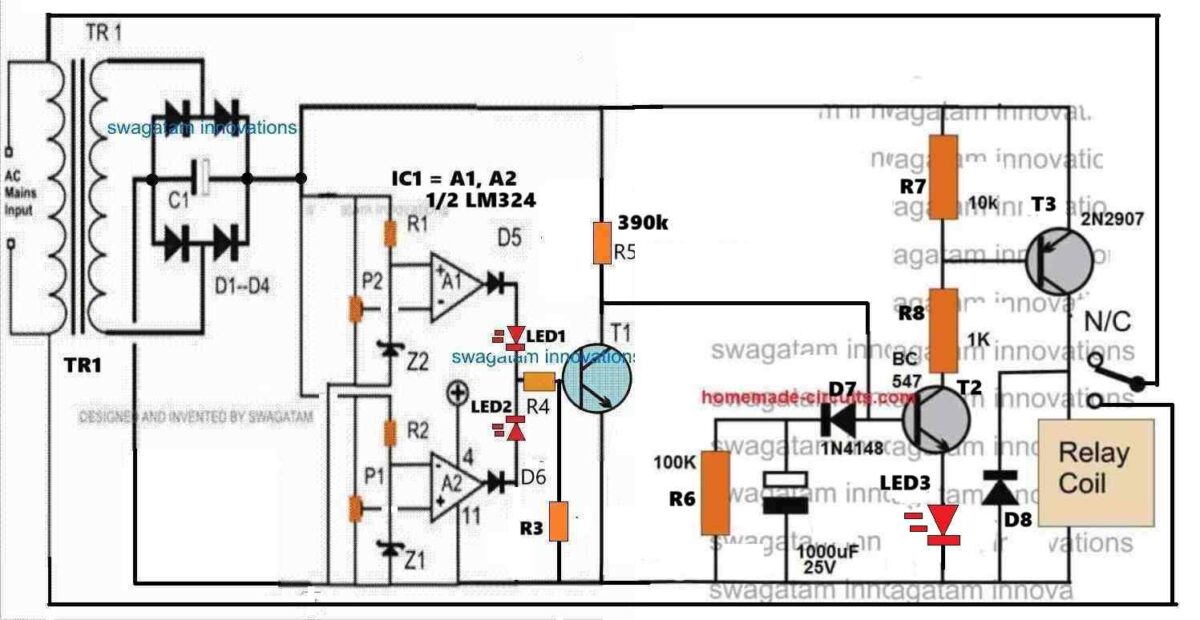
Home Protector Circuit with Extended Delay ON Surge Protection
In case the AC mains power outages are frequent and inconsistent in your area, you may want to have the delay ON surge protection time to be longer.
As suggested and confirmed by Mr. Ali who is a dedicated reader of this blog, the following home protector design can be used for implementing a much longer delay ON time surge protection.
Video Test Results
The following video shows the basic testing procedure of the above explained home protector circuit. The video was contributed by Mr. Ali.
A heartfelt thanks to Mr. Ali for his hard work. His testing and video contribution to homemade-circuits.com are much appreciated.
Conclusion
The above explained mains AC home protector circuit can be built and installed in homes for getting a full fledged protection from fluctuating high and low voltage situations and from sudden voltage in rush during power outages. If you have any further questions and doubts regarding the above concept, feel absolutely free to contact me through the below given comment box.


Comments
greetings..!!!
dear Swagatham,
Thanks alot for such professional stabiliser circuit as home protector.I have some modifications. first of centre of high low preset fix an 22mfd capacitor to ground both high and low preset moreover the base of BD140 to ground was 1k but change that value to 2k2 to increase the life span of led.And connect 100mfd capacitor across relay point.Then this circuit will work extraordinary results. (This is the circuit with transformer and BD140 and 7812)my humble request is make all this circuit together named under home protector headline .so easy to try one by one.Anyway thanks alot such amazing circuit.
Thank you so much Dr.Sison, I greatly appreciate your kind feedback and the improvements you have suggested.
I hope the readers will take note of these suggestions and do the procedures accordingly.
When I have time I will surely consider updating all the diagrams in the comments section in the above article….
Hi.
First of all, thank you for sharing such wonderful information.
The current load of the house is sometimes 60 amps. Can the relay cut off this load in the circuit you share?Is the load capacity that the relay can handle in closed contact greater than in open contact?
Hi, you are most welcome….yes, the relay can handle this much load, if the relay is rated at 100 amps…
The relay is handling the full load when it is closed in N/O position…
sir can i use 50k instead of 22k? also 22uf400v is blast. can i use 100uf 420volt, and imstead if 105j can i use same 0.33uf? 105j 400volt is giving 131volts, mqy be due to this its happen…..
Yes, you can use 50k instead of 22k preset.
2uF/400V shouldn’t have blasted because the maximum rectified output DC from a 230C AC is 310V only, which is less than its 400V rating.
Anyway, you can use 100uF/420V.
105 cannot give 131V, it should produce 310V at the 220k upper end, assuming the input is 220V AC. You can try 0.33uF and check whether it gives 310V DC at the 220k upper end or not.
And, the P1, P2 must be preferably replaced with 100k presets to avoid voltage drop at the 220k/50k junction, so if possible use 100k presets for P1 and P2.
sir i assembled all components as your diagram, delay time is working, but unable to check low and high volt without variac, but i am getting 22uf 400volt capister is heating.its connected with 105j 400volt capister.
Ghulam, Please check the following updated diagram:
https://www.homemade-circuits.com/wp-content/uploads/2024/07/transformerless-AC-mains-220v-home-protector-circuit-with-SSR.jpg
Here, I have replaced the 10k preset associated with the 220k resistor with a 22k preset which can be used to adjust and set the high/low voltage thresholds.
Also in this diagram you can see that junction of 220k/22k preset is connected only to the presets P1 and P2 and NOT to the opamp zener diode resistors.
The zener diode resistors are directly connected to the other separate positive line.
In this way the 220k/22k(preset) junction sensing voltage will not get affected by any external elements and will provide the correct sensing voltage to the opamp.
How to setup
Initially keep the 22k preset wiper to ground level.
Suppose the normal input is 220V or 230V AC, now adjust the 22k preset until the junction of 220k/22k becomes around 14V.
So now 14V corresponds to 220V AC input.
With the above information in hand we want to calculate the high/low thresholds at the 220k/22k junction.
Let’s say we want the high cut-off at 270V and low cut off at 180V, we can find the equivalent DC at the junction of 220k/22k using the following calculations:
High level cut-off DC threshold
220/270 = 14/H
H = 17V
So in this example 17V corresponds to high equivalent at which the opamp must cut-off and produce a high at its pin#7 output.
Low level cut-off
220/180 = 14/L
L = 11.5V
So in this example 11.5V corresponds to low DC equivalent at which the opamp must cut-off and produce a high at its pin#1 output.
Using the above data, you can now set the P1 and P2 presets for fixing the opamp low/high cut-off points.
Once done, you can confirm whether or not the opamp is responding to the cut-offs, by moving the 22k preset up/down and by checking whether or not the opamp output HIGH/LOW LEDs are correctly switching ON/OFF at the relevant DC cut-off thresholds.
The 105/400V capacitor corresponds to 1uF/400V which looks unnecessarily high value, you can try 0.47uF/400V instead. However if you don’t have a 0.47uF you can carry on with the existing 105.
sir this is for confirmation. i used 105j 400v with 22uf 400v, and 334j 400v with 100uf 420volt, at 105j i am getting 131 volts, 100uf 420volt at positive connected 100ohm and connect 24 volt zener with 100uf 25volt, getting 24.2 volts, then i connected 12 volt zener, without 100uf 25 volts. then i am getting at 24 volts zener 13.2, and 12 volt zener getting 12.2volts,
is it ok? with 12volt zener need to connect 100uf 25 volt or no need?
thank you sir, i will update you once its done, sir how we can set high and low voltage in this version?
No problem Ghulam!
Ideally, to set the low/high cut-offs in this circuit you will need a Variac, a fan regulator cannot be used.
Alternatively, you can replace the 10k resistor associated with the 220k resistor with a 10k preset, then adjust this preset to get the desired low/high thresholds at the JUNCTION of the 220k/10kpreset, and then adjust the P1 and P2 accordingly to set the high low cut-off points. Be extremely careful, because the circuit is not isolated from 220V mains…
sir then how we can use two bridge, while i am using SSR with bt136, as my assembled, with two 0.33uf 400v bridge and 22uf 400v positve i connected with 100ohm, and op amp positive given from 24 zenor. and ground to opamp ground. then again 100ohm conected with 22uf 400v with 12volt zenor. this point connected with bd140 emiter. as this setup i used fan regulater and low cut is working. but unable to check high voltage because fan regulater given 235 volt max,
in this situation if i use 220k and 10k then i am unabled to setup low and high voltage.
Ok, here’s the updated design yo can try:
https://www.homemade-circuits.com/wp-content/uploads/2024/07/solid-state-SSR-AC-mains-home-protector-circuit.jpg
Hello Ghulam,
I will provide you the diagram using an SSR. I will let you know once it is done.
hello sir, sir i removed 220k and 10k and directly connected positive and ground. its working perfect with high volt cut, but at low volt, normal led is dim while voltage low, not properly off, and if i used 1k resister from ic 555 pin 3 to moc3021 pin 1, voltage showing after 1k at moc3021 pin 1, 1.1volt, if i removed 1k then voltage showing 11.7 volt, but i think in this situation moc3021 not in safe stage, what i do for safety of moc3021?
also guide me 220k and 10k removed is ok or its harmfull for circut?
Ghulam, the 220k/10k can be removed only if the circuit is powered by a transformer/bridge. If you are using capacitive power supply then the 220k/10k resistive divider is a must for dropping the detection voltage to the op amps, if you remove it, the opamp will burn.
The 1.1V after the 1k is correct because the internal LED of the MOC3021 is dropping the voltage to the forward voltage level of the internal LED. If you remove the 1k, the MOC3021 internal LED may burn.
The “NORMAL” LED will shut off only if the emitter voltage of the BD140 is at least 3V lower than the voltage supplied to the Vcc pin of the opamp.
hi sir, hope all is going well. sir i am sorry for trouble you. but i want to make this project succes. i am facing issue with cuttoff stage, i used two 0.33uf 400 volt in parallel, and 22uf 400 volt capister, getting 17volt, i disconnect from bridge, and connected variable supply set at 20volt for high cut, moving vr for high cut, its just normal led glows, same thing at low (14volt)voltage, i connected positive of both VR joint of 220k and 10k.where ic pin 6 and 3 are connected with 10 k fixed resister, as per diagram. as you suggest i used ssr for load.
other end its working with transformer version which you sent with 7812. plz make it easy for me…..
i am stuck with this project….i used single bridge with two 0.33uf 400volt.
Hi Ghulam, If you are using a variable DC 20V power supply for setting the preset, then it cannot be connected to the 220k/10k resistor divider because that divider is for sensing 310V DC input from the 0.33uF/400V capacitor.
And the voltage across the 22uF/400V must be 310V, if your input supply is 220V AC, it cannot be 17V.
That is why I think we need a separate capacitor bridge supply for the 220k/10k sensing input, and a separate capacitor/bridge for the BD140, 555 and the SSR stages.
hi sir,
sir problem is in the voltage, i checked as you guide, delay timer is working, at 555 ic voltage is 5.7. and at the bridge of 0.33uf voltage is 6.8, i tried with 105j instead of 0.33uf, voltage same, but if i used 225j instead of 105, 100ohm resistance burn which is connected with positive and 24v zenor, due to low voltage cut off also not working…..
OK, good, so that means delay is working. With 205 capacitor the 100ohm will certainly burn or there will unnecessary heat dissipation, so I think you can try connecting another 0.33uF parallel with the existing 0.33uF capacitor to make the 555 DC supply perfect, or a 0.47uF/400V will also do.
Now please check the high low cut-off by adjusting the P1, P2 presets, and check whether the High, Low, and Normal LEDs are switching correctly or not.
Another thing is that, if you use a Triac instead of a Relay for switching the output load then a single bridge/capacitor will be sufficient, no need of two separate bridge power supply configurations. Also the 2N2222 can be avoided if a triac is used.
Triac will also make the whole unit perfectly sold-state and very compact.
no sir delay time is not working, relay direct on once we give power. bcause we are giving positive through bridge.
sir what is the purpose of 2 bridges, and also why can we use 1 bridge with 225j 400v and 10uf 400volt and 24 volt zenor, also with pnp collecter can we connect 12 volt zenor for delay timer, is it possible?
Please connect an LED in series with the 2N2222 base and check whether the LED is glowing or not, if yes, try short circuiting the base/emitter of 2N2222 and check whether the relay is switching OFF or not this will prove 2N2222 is burned or is good. and also check the voltage across the 555 IC.
Relay requires high current whereas IC circuits require low current, that is why separate bridge supplies are used.
If you use single high current capacitor bridge then the IC or the zener might burn or the series resistors might heat up and burn.
Afterwards you can try single bridge supply….
hi sir, sir i assembled transformerless version,i didnot get 2uf 400volt, instead of this i used 225j 400volt and 0.33uf400volt instead of this i used 334j 400volt. i used 10uf 400volt with both bridge, which is connected with 334j 400 volt bridge i am getting 15.4 volt, and another bridge which is connected with 225j 400volt, i am getting 131 volt, once i connected bridge positive to relay positive with in4007 diode as u show in the diagram, 1k resister which is connected with relay led, that is burned. may be due to high voltage(131volt),and the other end at 12volt zenor voltage getting 12 volt, but at 24volt zenor voltage is 15.4 almost.
plz guide me, weather componnets are ok or not?
Hi Ghulam, With reference to this diagram, your part vaalues look OK to me.
Is the relay operating? If yes, then try decreasing the 225 value to 105 or 1uF/400V, and check again if the relay is operating correctly or not.
Is the delay feature working?
If yes, then your circuit working OK.
But 24V should not drop to 15V. It might be happening because the 0.33uF capacitor current output is not sufficient to drive the op-amp IC and the BD140/555 stages together.
Try adding another 0.33uF/400V in parallel with the existing 0.33uf/400V capacitor and check whether it increases the voltage across the 24V zener diode or not?
thank you sir
thank you sir, once i completed i will update you, sir with both bridge rectifier filter capister is required or not? in diagram not mentioned filter capister.
Hi Ghulam,
I am sorry, I forgot to show the capacitors across the bridge rectifiers.
For both the bridge rectifiers you can connect 100uF/400V capacitors, across their positive and negative terminals. If 100uF/400V is not available you can use any lower uF value also, but the voltage must be 400V.
Additionally, please connect a 1000uF/50V across the relay coil.
And a 100uF/50V across the 24v zener and 12V zener each.
ok si, thank you, i will update you soon
ok, no problem.
sir over and under voltage section is easy for me, plz give me transformerless power suply version. i am sorry for all troubles which i create for you. and also thanks for your passion.
sir i connect led with base of 2n2222, led glow but once i short with emiter lee is off not relay, then i change 2n2222, i found 2n2222 is heating…..also delay time not working.
Ghulam, Please keep the relay disconnected from the 2N2222 temporarily, and keep the 2N2222 also disconnected from the IC 555 pin#3
Now connect an LED between pin#3 and ground through a 1k resistor.
Now check the delay effect on this LED.
Please check the voltage across the 555 IC (+) and ground terminals.
Keep the meter connected across the 555 supply pins and check the response when you first switch ON power.
Also make sure the “NORMAL” LED is ON.
Ghulam, please try to reply under the correct thread, or create a new thread, otherwise the comment sequence breaks and becomes difficult to understand..
Hi Ghulam, Ok, i will do the transformerless version soon, and let you know once it is done…
Hi Ghulam, I have designed the transformerless version, as given in the following link:
https://www.homemade-circuits.com/wp-content/uploads/2024/07/transformerless-home-protector-circuit.jpg
Please build it very carefully, and don’t make any mistakes.
Keep a watch on the 2N2222 relay driver transistor, and check if it blows or not, mostly it won’t.
Please remember that the entire circuit would be floating with mains 220V AC, so be extremely careful while testing the circuit in powered ON condition.
sir i disconnected opto copler, and bt169 from relay transister, then with led positive connected 1k resister and connect with capister positive which is connected with bridge in4148, and led negative with negitive, then supply on ,after delay relay is on, then i connected mobile charger as a load, its showing 0.2, then as load i used 40watt soldering iron, voltage same 0.2,
is there any other way to control current? like with 555 ic or lm358? may be this i am not understanding. its humble request plz test this circut with you and provide me diagram with final compnents. then i will make all connections and check. plz its request
Hi Ghulam,
You must understand the working, then it will be easier for you to troubleshoot it.
It is basic Ohms law, that when current passes through a resistor, it develops a proportionate amount of voltage across it.
Please disconnect the 1N4148 bridge across the Rx resistor and measure the voltage directly across the RX resistor with an AC Voltmeter.
If still there’s no change in voltage with respect to load, then I cannot help, you will have to cancel the over load feature and stay only with the over/under voltage, and with transfomerless version.
For the transformerless version also, you must first understand how the circuit works and only then try it.
hi sir, i checked voltage, its showing 0.2, i disconnect opto copler and bt169 from relay transister base, at in4148 bridge 100uf already connected, led connected with 1k resister, its showing 0.2, i dont know its checked correctly or not, plz guide me
otherwise plz provide me transformerless supply version with over under voltage protection plz
Hi Ghulam, how much load did you connect with the relay N/O contacts. Please check the voltage by increasing the load, as the load increases the voltage must also increase proportionately.
sir for testing voltage at in4148 100uf caposter should be connected with in4148 bridge rectifier or not?opt coupler completly need to disconnect from bridge?
Yes, 100uF must be connected across the RX bridge rectifier and the opto-coupler completely disconnected.
sir i tried with 0.47 ohm 5 watt, as load i checked with water moter, its taking almost 9amp normally, when i start moter, relay flicker and cutt off, when moter off relay auto on at same time,then i removed bt169 from base of relay transister(bc547) to make sure relay can run moter or not, but in4148 burned which is connected with RX, as i am using 30 amp relay……its relay issue or some where else?
Hi Ghulam,
You must first check the voltage across the 1N4148 diode by connecting an LED and disconnecting the opto-coupler and the SCR.
You must go step by step.
1N4148 bridge cannot burn unless its output is short circuited, so I am not sure how your 1N4148 bridge rectifier burned?
A motor will draw high current initially, and then settle down to normal current, so at start up the motor current can be very high.
Please check using only bridge rectifier and LED (use series 1k resistor instead of 100 ohm for better safety).
sir i am using quarter watt RX. i have 0.47 ohm 5 watt resister, can i check with that?
Yes, you can use that resistor…but with a 0.47ohm resistor you may need above 1000 watt load to test.
0.47 = 2.5 / I
I = 2.5 / 0.47 = 5 ampere
5 * 220V = 1100 watts
thank you sir, actually sir RX value is confusing, first i was using 3.3ohm, it was cuttoff on mobile charger, and 100watt bulb, but 40 watt and 60 watt was working, then i changed RX 3.3 to 2.2 ohm, i connect load combine iron, 100 watt bulb, 400watt drill, all load works together. then again i changed 3.3. now also not cutt off. thats why i am confusing, if you can provide me exact value of RX for 25 amp, and guide me for load, at how much load its cutt off, then i will check and add feature..plz
Ghulam, what is the wattage of the resistor you are using?
Make sure to use a high watt resistors such as 2 watt or 5 watt.
Only by measuring the voltage across the bridge rectifier will tell you whether the resistor/bridge configuration is correct or not.
Or disconnect the bridge from the opto-coupler and connect an LED/resistor across the bridge as suggested earlier.
sir i did but led not glow, yes i am using 100 ohms resister with led. sir may be this is high level. may be i cant make, sir is it possible provide me transformerless power supply with only over and under voltage plz due to my less knwlodge i am disturbing you much, i am sorry plz
Ok, no problem, if you are finding the overload feature difficult to implement, you can leave it.
I will try to design the transformerless version soon, and let you know once it is done…
Hi Ghulam,
The idea is very basic.
The RX resistor develops a voltage across itself which is proportionate to the load current, as the load current increases the voltage across the RX resistor also increases proportionately.
Please disconnect the bridge rectifier output from the opto-coupler and check the LED glow again.
I hope you have connected a series 100 ohm resistor with the LED.
If it is a 3V LED, it will require around 2.5V to start glowing, so the minimum RX value should be:
RX = 2.5 / load current