In this post I have explained a relatively easy lipo battery balance charger circuit which is designed to continuously scan and charge the connected cells of the battery.
The idea was requested by Mr. Schindler and Mr. Emil Jan Thomas Baticulon.
Charging 6 Li-Po Packs
The concepts are very well written, concise and clear. Thank you so much for the deep coverage of the charging subject.
Have you encountered the need to charge several identical lipo packs regularly? I have that very need, it is time consuming to recharge 6 high power packs containing 4 cells each every few days.
I propose a single cell charger that scans all cells via the balance plugs and serves up the requirement per need during a partitioned interval of the scan period.
Arduino sketch, shift registers, discrete coupling and a plan to stitch it together... there is where I bid you to guide me to a viable implementation. If you'd be so kind?
Charging 18650 Li-Ion Pack
Good day,
I just recently found your blog and upon further reading your post it's very helpful with or without electronic background and i appreciate your work.
I have a project in mind but I am stuck with it, My idea was how can I charge 13pcs 18650 li-on battery in series connection with balancing charger?. Can you help me with it and add this to your work?
Thank you,
The Design and Working
As shown in the following diagram, the proposed Lipo battery balance charger circuit can be implemented rather effortlessly using a couple of IC stages.
Let's try to understand how the circuit is intended to function:
- You can see two DC supply sources in the circuit. One is a fixed 12V for the ICs and the relay driver stages, second is the 4.2V for charging the Lipo cells through the relay contacts. (Make sure to connect the grounds or the negatives of both the supplies together in common)
- This 4.2V is also fed to the non-inverting pin#3 of the op amp via the preset.
- Referring to the circuit diagram below, when power is switched ON, a HIGH signal from one of the IC 4017 outputs randomly switches ON one of the relays through the connected BC547 driver.
- The relay contacts connects the 4.2 V to the relevant Lipo cell. If the cell is discharged it causes the 4.2 V to instantly drop to its discharged level, which may be anywhere from 3 V to 3.9 V.
- This drop causes the op amp pin#3 potential to drop below its pin#2 potential.
- Due to this, the output of the op amp goes low, which does not have any effect on pin#14 of the IC 4017.
- This situation allows the connected Lipo cell to start charging, and as a soon as it reaches the 4.2 V mark, as per the setting of the preset, pin#3 potential goes higher than pin#2 potential.
- This instantly turns the output of the op amp high, toggling pin#14 of the IC 4017 with a clock pulse.
- The above action causes the existing output pin HIGH from the IC 4017 to shift to its next pinout.
- This HIGH causes the next relevant BC547 relay stage to switch ON and connect the next Lipo cell in the same way as explained above.
- The cycle keeps repeating for all the 10 cells, until all the cells charged sequentially.
Control Circuit Diagram
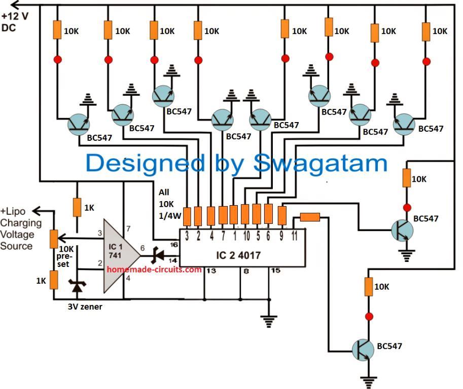
The second diagram below is the relay driver stage which needs to be repeated 10 times and the base of the BC557 associated with the red spots of the relevant BC547 stages from the first circuit below.
Relay Driver Schematic
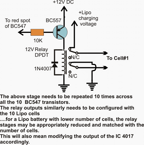
If the cells are 3.7V rated, the opamp preset is adjusted such that its output pin#6 just goes high when the charge level across the cell reaches around 4.2V.
How to Set up the Balance Charger Circuit
For setting this up, a sample 4.2V may be fed at the shown preset's upper lead, and the preset slider adjusted to make pin#6 of the opamp just high (positive).
- With all the positions connected as depicted in the diagrams and power switched ON, let's assume that at the onset pin#3 of the IC4017 is high which in turns activates the associated BC547, BC557 and the connected relay contacts.
- Cell#1 now begins charging, which drags down the supply voltage across the preset pin#3 of the opamp to may be say 3.4V or whatever may be the initial discharge level of the cell#1.
- While this happens, pin#3 of the opamp experiences a lower potential than it's pin#2 ensuring a low signal at its pin#6 and the pin#14 of the IC 4017.
- As cell#1 of the lipo battery charges, the terminal voltage of this cell slowly increases until it reaches the stipulated 4.2V mark.
- As soon as this happens, pin#3 of the opamp also is subjected at this voltage forcing its output pin#6 to go high, which in turn prompts the IC4017 to shift its pin#3 logic high to it next pin#2, toggling the driver stage of this pin into action.
- The above shift activates the charging of the second cell of the lipo battery in the same manner as it did for the first cell.
- The process now continues and repeats itself by scanning and charging the cells in steps continuously.
- Thus the lipo battery cells are maintained with optimal charging level through the above explained lipo battery balance charger circuit as long as the circuit remains connected with the lipo cells.
Question from Avid Reader Mr. Prithviraj
I am an avid follower of your website www.homemade-circuits.com. Your circuits are always working and awesome for a hobbyist like me to learn and try. I need a small guidance on a question I have regarding LiPo Battery pack.
I am trying to make an e-Bike on my own. I'm building a 24V 6S 18Amp Lithium Ion battery pack which will contain a BMS board for balance charging. My question is, if I try to charge this battery pack directly with a 24V 10A SMPS will that be safe?
I mean, since I already have a BMS built into the battery pack, can I directly connect the SMPS output to the battery pack input/output lines? I am using a 20A 6S BMS in the battery pack. So, also please advise if the 10Amp charger taking is safe too. I will be really grateful if you could please advise.
My Reply:
Yes, you can use the 24V SMPS for charging the mentioned battery. The battery will be safely charged since a BMS is already present in the system.



Questions & Answers
Gday Swagatam,
Just a query on this and your article on ((Lipo) Battery Charger Circuit).
It seems you have it so only 1 cell at a time is getting charged with this, would it be possible to adapt this to have all cells charging at the same time?
Otherwise, following your other article, would this work;
Supply 4.2v to each cell and have a cutoff trigger of 12.6v, checked against the whole pack assuming 3s?
Hi Daniel,
charging all the cells together might not be feasible, because the positive of one cell is the negiative of the next cell, so charging them together can cause short circuit acroos the terinals, so according to me that's not possible and not recommended.
charging the whole unit with a single supply is the ordinary method that people usually implement, but that has severe drawbacks and that's why the above circuit was designed to ensure individual charging of the cells and ensure max efficiency and long life for the cells
Hi,
according to my knowledge, you can safely charge series connected cells by using independent chargers and galvanic separated power supplies for each charger. For example 6 series battery -> 6 chargers -> 6 PSUs. Use for this 7-pin cable, where:
1. pin = 1. cell/charger “-”
2. pin = 1. cell/charger “+” and at the same time 2. cell/charger “-”
3. pin = 2. cell/charger “+” and at the same time 3. cell/charger “-”
4. pin = 3. cell/charger “+” and at the same time 4. cell/charger “-”
5. pin = 4. cell/charger “+” and at the same time 5. cell/charger “-”
6. pin = 5. cell/charger “+” and at the same time 6. cell/charger “-”
7. pin = 6. cell/charger “+”
Please correct me if I am wrong 🙂
Yeah, that looks feasible. Each power supply should have its own current control and auto cut-off, and precisely adjusted to produce exactly the same voltage.
Hi thank you for your post.
I couldn't understand how to choose battery for op-amp noninverse input. Dont we need to set a circuit for switching between batteries.
Hi, thanks, the switching between the cells is done by the relay….please read the article completely for the details.
the source voltage at the non-inverting pin is supposed to be from the selected charger power supply source.
Hii sir,
Thank you verymuch
you are welcome!
Hi
Awesome circuit! Question:
– For any channel, when it’s counter-pin goes hi, its BC557 turns on, which turns on its BC547, which turns on its relay. Correct?
– Is it possible for the BC557 to drive the relay directly, and remove the BC547 from the circuit?
thx!
Hi Thanks,
actually it’s the opposite, during a high state of the 4017 output pin, the relevant BC547 is triggered ON, which in turn triggers the associated BC557, therefore BC557 cannot be directly used with the 4017 outputs.
Is it necessary to use an SCR or Triac? Or will any transistor work, with sufficient current-capacity?
thx!
any low power transistor will work, which may be similar to BC547/557
hello Swagatam, i am trying to get a battery balancer for 12v battery is series in a 24v circuit. When charging with the inverter,it should be balancing both batteries at same voltage. i dont understand how to use this circuit to get this done..what values of resistor am i using? can i still use this mosftets and transistors?
thanks
hello kentro, the above circuit is intended for balance charging batteries in series, I could not get how many batteries you have used in your battery set. you are saying “a 12V battery in series with a 24V circuit” sorry I could not understand this statement, please clarify this.
do you mean a 12V battery in series with a 24V battery?
Oh! i am sorry…i meant two 12v batteries is series.
thanks for ur prompt response
OK, for two batteries also you can use the above circuit with a slight modification. Use the outputs at pin#3 and pin#2 and eliminate the remaining outputs.
to ensure automatic changeover disconnect pin#15 from ground and connect it with pin#4 of the IC
integrate two relay stage with the BC547 BJTs attached with the above mentioned pinouts, finally configure the contacts with the respective battery terminals.
I have a 6s Tattu 16000mah (6 cells connected in series) Li-Po Battery with 2 main +ve and -ve terminal and balancer connector. Do above circuit can charge my battery? The battery’s balance connector should connect to which part of the circuit above?
Yes circuit will charge your battery but this circuit is for those who have advanced knowledge of electronics and opamps, because adjusting the preset and setting up the circuit is crucial here….
Can you tell me some example of “adjusting the preset” and “setting up the circuit”, I’m newbie, thanks.
It is already explained in the article thoroughly…
a sample 4.2V may be fed at the shown preset’s upper lead, and the preset slider adjusted to make pin#6 of the opamp just high.
Can u further explain these 2 sentences? From my current understanding, at initially the 4.2V (from power supply) will feed to the pin3 of the opamp, and the “slider” will adjust the 4.2V to further higher volt/lower volt in order to make the pin6 of opamp output a high signal. What is the slider? a potentiometer?
————————————————————————–
What mean by Li-po charging voltage source (that feed to the pin3 of opamp)? Is it a lab bench power supply with voltage fixed to 4.2V? This charging source can be non-constant output power source such as solar generator which its output depend on current light intensity.
Is it the Li-po charging voltage source is the same source with the Li-Po charging voltage feed into the cell#1.
Teoh, your understanding is mostly correct regarding the mentioned specs.
4.2V should be from a constant voltage and constant current source, as per the battery specs.
the slider means the moving shaft of the preset connected with the opamp, which is moved by the screwedriver
the 4.2V supply source to the opamp and the relay are the same….and should be taken from the same supply source.
Good Day Sir..
If my lipo pack is 4S can i modify this circuit by using only pin 1-4 of 4017?
And 4 relay circuit?
Thanks
Paul
yes definitely you can modify the design appropriately for any Li-po battery pack having cells between 2 and 10….
As the lipo batteries get closer to the 4.2 volt level are we not supposed to reduce the constant current as it gets closer to this level. Is there a way to include that in this circuit. Or is that not so important.
constant current does not mean the current would be forced at that level constantly, no. Constant current means, the specified maximum amount of current level will never be allowed to increase by the source, or and will be restricted at the specified level..
It is the load which decides how much current it has to consume from the source, provided the voltage is maintained at the right level.
Here since the input is fixed at 4.2V which is compatible with the Lipo rating, the current is automatically shut down by the Lipo when it reaches the 4.2V mark.
The constant current could become dangerous if the input voltage is increased above the 4.2V mark.
Therefore current reduction is not required, the battery will take care of it automatically, however once 4.2V level is reached the supply must be immediately switched OFF
Many thanks I now understand. So once voltage reaches the value set by potentiometer at pin 3 then voltages are both equal to 4.2 so no more current is then able to flow. Makes perfect sense. As it always needs a voltage difference for charge to flow.
So initially on charging at the very start the current is at a fixed rate below a specified level, in other words not say 3amps or something too high. Hence is current limited by the opamp?
Glad you found my reply useful….yes that’s exactly what I wanted to explain.
Whether it is at the start or at the end, the charging current consumption rate is determined by the battery’s internal chemical reactions, the constant current feature just makes sure that under any circumstances the current is never allowed to exceed the safe limit, let’s say if the current is selected to restrict at 3 amps then this value will be never exceeded by the CC source, but within this 3 amp value it is the battery which decides how much current it needs to consume throughout its charging period.
Sir can you post a Lifepo4 battery discharge circuit.
3.2 volt 5000mah.
Ajit,
Lifepo4 is also a type of Li-ion cell, so you can use any of the designs explained in the following article:
https://www.homemade-circuits.com/simplest-safest-li-ion-battery-charger/
Just make sure to keep the charging voltage to a fixed 4.1 V value, and the current to less than 50% of its Ah value.
Sir, First of all I don’t understand the preset value for the OPAMP ‘s non-inverting input. How can I select that voltage by using this POT(slider). My understanding is that we should make the voltage on the non inverting part little more than 3V because we have an preset value 3 at inverting pin. After that battery pluged in to the circuit we have an voltage drop on the pot, so the output of the opamp will be low until the battery reaches to 4.2 which makes our non-inverting input reaches its previous value that makes output of the opamp high. My understanding is correct or not? Thank you so much for your respond already.
Guney, your understanding is correct, the preset value can be a 10k preset
Good day Swag, well done for this update. Please how can I configure this circuit for 4 12v batteries in series to make 48v.
Thanks Adeyemi, for 4 outputs you just have to disconnect pin15 of IC 4017 from the ground and connect it with its pin1, then use the relay drivers for the pin3,2,4 and 7
Thanks Swag ,please is balancer necessary for 24v system
Adeyami, if it has series cells in it then it will be necessary.
Thanks sir
Good day Swag, please can you help me to design a balancer that works with the mechanism in the link below that works in balancing all cells as a whole at the same time.
A design that transfer excess charge to equalize all cells.
Thanks sir.
Sorry Adeyemi, presently I do not have the idea to design a circuit that will balance all the cells simultaneously…
OK sir, is there any advice or crude way of balancing lead acid batteries in series. Thanks Swag
Adeyemi, It has to be done in the way explained in the above article, which is very accurate and safe…any other method can be difficult to implement or risky.
With this circuit above, please I want to clarify some things.
1.for 48v battery system, for the DC supplies, one will be 12v supply for the IC, second DC supply will be what for charging the 4x12v battery in series.
2. Will there be balancing effect during discharge.
Thanks sir, Swag
Adeyemi, Discharging is not done through individual batteries rather directly from the combined series battery’s end to end points. So balancing cannot be implemented while discharging.
3. Please for the 48v battery system, is it possible to have main 48v charger system and 12v charging system for the balancing.
I have not fully understood the mechanism
Thanks sir, please how can I use this balancer for solar system. No grid supply around
You can do it in the same way as explained in the article…You will need two controllers, one for the battery and one for the IC circuit.
Hello,
I do not really understand to what voltage I should adjust the preset pot.I have read the whole article about 3 times, however, it still doesn’t make sense to, can’t figure out to what voltage I should adjust it if my batteries have a nominal of 3.7 and max charged voltage of 4.2.Can you please explain to me how to work it out?
Hello, this circuit is for people who have a good knowledge of electronics, if you cannot understand then you should not attempt it.
It is 4.2V at which the the charger must cut off…so 4.2V is the max threshold.
Hi,
thank you for your advice:). I think that I just figured it out, the op-amp, compares the 4.2 to the batteries voltage and tells the 4017 to stop charging when the comparing has shown that the battery is at 4.2 volts?
Is my understanding sort of correct, or I am completely wrong? And also about the present, how do I measure that the output is high, is it like binary to measure with an oscilloscope? Have a good one :).
When the opamp detects 4.2V, it sends a pulse to the IC 4017 so that its output moves to the next lipo cell and connects its status with the op amp input so that the opamp now starts scanning this new cell’s charging status, until it get fully charged at 4.2 V and the cycle continues.
To measure the instantaneous voltage of a connected cell, you can attach a voltmeter or an oscilloscope across the input supply source for the lipo