In few of my previous articles I have explained a handful of GSM remote control circuits using ordinary cell phones as the modem. All those designs incorporated the ringtone of the cell phone as the triggering signal. In this post we'll learn how the same could be achieved but by using the vibrator feature of the modem cell phone.
Using the Vibration Mode as Trigger
In our previous GSM remote control designs we used those cellphones as the modem which had the specific ringtone selection facility for a specific assigned number, here the modem will need to have a vibrating feature for the specific assigned number selected as the triggering number, this is important in order to achieve a fool proof operation of the system.
The idea is simple, it's to detect the vibration from the cell phone body, convert it into a toggling signal and control the desired load or gadget ON or OFF.
For detecting and using a vibration signal to trigger a relay, we'll need a vibration detector circuit as shown in the following diagram:
Circuit Diagram
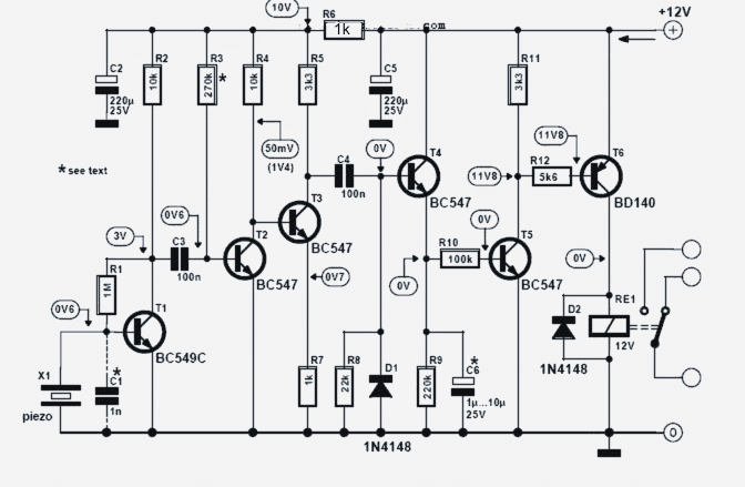
Transistor Amplifier
The circuit is basically a transistorized high gain amplifier where a piezo is used as the vibration sensor.
The vibrations from the piezo generates a correspondingly oscillating voltage at the base of T1 which is appropriately amplified by all the following transistor stages consisting of T2, T3, T4, T5, T6 and the associated parts.
The amplified DC signal is finally applied across the connected relay which toggles in response to the detected vibrations over the piezo.
Since a cell phone vibration could have an inconsistent vibrating rate could result in a corresponding oscillatory response over the relay switching.
To avoid this a high value capacitor in the range of 500uF should be connected directly across the base and emitter of T6, this will ensure that T6 sustains its conduction even while the cell phone vibrations are intermittently absent.
The Flip Flop Circuit
In the above mode, the relay stays activated only for so long as the vibration signals are produced, in order to translate the reaction into a toggling effect a flip flop circuit becomes imperative. The following simple 4093 IC based design becomes perfectly compatible for the required conversions.

The input trigger may be connected to the pole of the relay, while the N/O of the relay will need to be connected with the positive of the supply.
Alternatively, the relay could be entirely eliminated, and the "input trigger" of the above flip flop circuit directly connected with the collector of T6.
Once this is done the relay would respond with alternate ON/OFF toggling motion each time the modem cellphone is called by the owner or the user.
The relay of the flip flop could be used for switching any desired appliance or in case it's deployed inside a vehicle could be implemented to operate the central locks and the ignition system for achieving a complete cell phone operated security feature.
Using Piezo as the Sensor
C1 in the first vibration detector circuit could be a 0.22uF capacitor and must be employed only if the piezo is terminated over a longer distance from the circuit, otherwise C1 could be ignored.
Preferably the piezo must be situated close with the circuit board.
The piezo transducer is a 27mm ordinary device which are normally using in piezo buzzer circuits.
It must be appropriately housed inside a plastic enclosure for ensuring an optimal response from it.
The entire unit may be further enclosed inside a plastic box with the piezo assembly stuck on inner top surface of the box.
The modem cellphone must be directly placed over the above enclosure right on the outer opposite surface of the piezo assembly (see figure below)
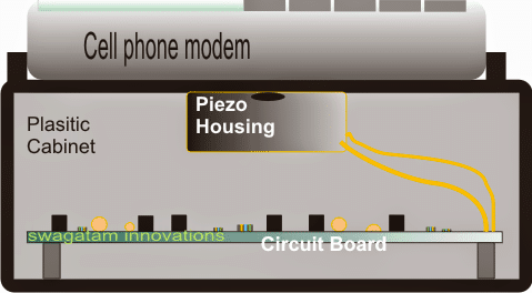
The modem must be appropriately secured over this position so that the unit does not tumble away from the box while vibrating.
Now your cellphone vibrator based remote control circuit is ready and may be used for any desired GSM based remote control application and may be switched from any part of the world, just with a flick of a button.
Make sure that the vibrator is assigned to turn ON only for the specific numbers and not for the default numbers to ensure a foolproof operation of the unit.


Questions & Answers
Hello,
I need some help putting together a lock system that I can open and close remotely via a cell phone. I have tried the internet but am unsure if any of the projects can fit my needs. It has to be dc and the lock must stay closed and only open for a brief period of time allowing access to the box. Once the box is closed again the lock must lock automatically, if possible. The device must be fairly small and fit into a suitcase about 1/2 the size of carry one suitcase. I need to lock up medications and restrict access until I release the meds for use.
Do you have any ideas that might help? I have very limited knowledge of electronics (1 EE course as an undergrad decades ago) but I can follow instructions fairly well.
Any help would be appreciated!
Hi, for that you will need a separate cellphone permanently connected with the receiver unit for operating the box lock. Also the attached phone must have a facility of producing a ringtone only for a specific number, and must remain muted for all other numbers. The specific number for which this receiver phone would respond will be your phone’s number. This ringtone can then be used for triggering the the receiver circuit and opening the box, so in this way it becomes a foolproof circuit
Thank you for your prompt reply again….I'll check as you said and provide feedback…
Dear Swagatam , I tried this. Very useful circuit indeed. The first part of the circuit
(vibration detector)working like a charm. But the flip flop is not working in my case. I
skipped the relay associated with the vibration detector and decided to use the the relay
of the flip flop to control the load but it's not working. Let me know if in the 4093 based
flip flop I should connect the pin 7 to the ground and pin 14 to the positive of the supply
as a standard configuration of the IC. I connected everything else as per your description.
Finding no clue what went wrong. Please help.
Sanjoy, remove the flip flop circuit from T6 and check it separately by manually touching the trigger input momentarily with the positive line. If the circuit does not respond then there could something not correct with your connections or the IC, confirm it by rechecking all the points….you can also check by connecting an LED in series with the base resistor R3 of T1, ths LED should illuminate ON/OFF in response to the triggers at the input of the flip flop circuit.
you don't have to connect anything across T6 collector and ground…it should be directly connected with the trigger input of the flip flop, and also remove the 470uF since there's already C6 present.
both the flip flop designs are absolutely correct and has been tested thoroughly, so both should work if done correctly.
Swagatam, I followed your reply but the flip flop is still not working.I used 1 nF polyester capacitor as c1, I tried changing the value to .22 mfd(although the length of the wire I connected between c1 and piezo element is around 2 inches only ) as well but not working. Again the 4017 based flip flop is also not working. In the 4017 based circuit I used a 12v smps adapter as the supply for the vibration detector and a 12 v / 500 mA transformer (as shown in the circuit)for the supply of flip flop.In the 4017 circuit I connected the trigger point to the collector of T6 directly. I am clueless where exactly it went wrong. Let me know one thing as I skipped the relay of the vibration detector while using it with flip flop for both the circuit should I connect the collector of T6 to the ground directly or should I connect the diode between collector and ground of the vibration detector. I am also using a 470 mfd/25v electrolytic cap between the base and emitter of T6 where I connected the positive of the cap. to the emitter side. Please help me correct the problem so that at least one of the flip flop circuits works correctly.
Thanks Sanjoy, I am glad to know that you could make it successfully.
yes definitely you'll need to connect the pin#7 and pin#14 of the IC to the supply rails, otherwise it just won't work, because these are the supply pinouts of the IC and needs to be connected with the respective supply rails.