The IC LM386 is a 8-pin tiny power amplifier chip, specially made for operating under relatively low voltage parameters, yet provide considerable amplification.
IC LM386 amplifier circuit becomes suitable for applying in small low power audio gadgets like in FM radios, door bells, telephones etc.
Let's begin the IC LM386 amplifier explanation by studying its absolute maximum ratings first, meaning the parameters which should not be exceeded while using this IC in any circuit:
Technical Specifications of IC LM386
- Supply Voltage: 4V to Max. 15V (Typical)
- Input Voltage: +/- 0.4 volts
- Storage Temperature: -65 degrees to +150degrees Celsius
- Operating Temperature: 0 to 70 degrees Celsius
- Power Output: 1.25 watts
- IC manufactured by: National Semiconductor
Internal Schematic
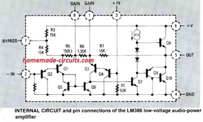
How to Control Gain for the IC LM386
In order to make the IC better with its response, its pin#1 and 8 have been attributed with a gain control facility which may be set externally.
Gain simply means the capacity or the amplifying level of the device up to which it is able to amplify the applied input low signal audio input.
When the above pin outs are kept unconnected to anything, the internal 1.35K resistor sets the gain of the IC to 20.
If a capacitor is joined across the above pin outs, the gain is suddenly lifted to 200.
The gain may be simply made adjustable by connecting a pot in series with the above explained capacitor across the pin 1 and 8.
Practical Application Amplifier Circuits Using the IC LM386
The following figure shows a typical IC LM386 amplifier circuit having the bare minimum number of components required to make the IC operate at its internally set level of gain 20.
Having Gain of 20
The speaker used is a 2 watt, 8 Ohms type.
The input at Vin may be fed from any audio source such as a cell phone headphone socket, a CD/DVD player RCA L or R socket or any other similar source.
The pin Vs should be connected to +12V DC supply from an AC DC adapter or a home made transformer/bridge power supply unit.
Pin #4 should be connected to ground or the negative of the power supply.
The earth wire or the negative wire from the input audio source should also be connected to the above negative of the power supply.
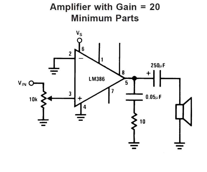
The input pin#2 goes to a 10K pot which becomes the volume control, one of its end terminals is picked for receiving the input signal while the other end is connected to ground, the center one goes to the hot end of the IC.
The speaker is connected to in #8 via a high value blocking capacitor, the resistor/capacitor arrangement connected across pin #5 and ground has been included for frequency compensation and to provide greater stability to the circuit.
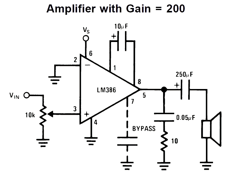
Having Gain of 200
The next circuit shows a similar design as above, except that its pins 1 and 8 have been connected to a capacitor of 10uF, which as explained above helps to pull the gain of the amplifier to 200
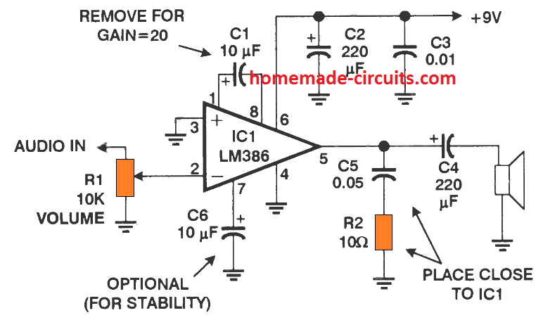
Detailed LM386 Circuit Diagram with Instructions
Application Circuits
From the above discussion we have learned that the LM386 is versatile little audio amplifier IC which can be applied in many different small audio related circuits quickly and with great efficiency.
The following are a few application circuits using IC LM386 which you an build and have a lot of fun.
MIC amplifier circuit using LM386 IC

The following image shows how the above explained LM386 may be applied for achieving a simple yet powerful microphone amplifier circuit as shown below
LM386 Amplifier with Bass Boost
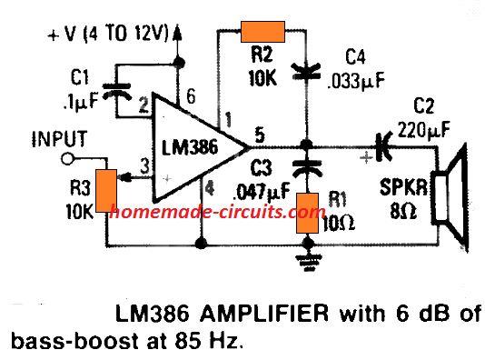
So far we know that attaching a 10-µF electrolytic across pins 1 and 8, it is possible to enhance the actual gain of the circuit to 200. This happens due to the capacitor appropriately shorting out the IC's in-built 1.35K resistor.
The figure above illustrates the way to shunt that resistor by implementing C4 -R2, to allow 6 -dB of bass boost at 85 Hz. This compensates the actual inability of the chip to produce suitable bass effect through typically used low-cost 8 ohm speakers.
AM Radio Circuit
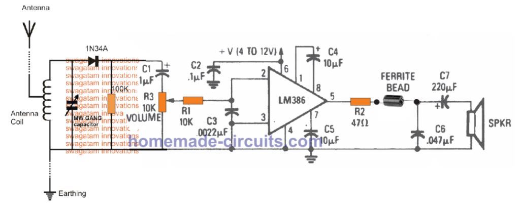
The figure above shows how the LM386 amplifier design could be customized like a compact amplifier for making a simple AM radio. Here, the detected AM transmission is supplied to the non-inverting input of the IC through volume control pot R3, and the resulting RF is de-coupled by way of R1, C3.
Any sort of left over RF disturbances are blocked from passing on to the loudspeaker through the indicated ferrite bead. In this LM386 AM radio design, the voltage gain of the IC is set at 200 through C4. You can also see that the circuit is supplied through supplemental power supply ripple rejection stage by configuring C5 between pin 7 and the negative line.
Infrared Decoder Amplifier
The next LM386 IC application circuit shows how the IC can be configured like an infrared receuver, amplifier and decoder.
Any infrared transmitter can be used to send the signal to this receiver. The LM386 receiver will receive the IR signals and convert them into audio signals through the connected loudspeaker.
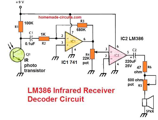
This receiver is intended to decode and demodulate all sorts of IR light beams that are amplitude-modulated (AM) and operate a loudspeaker. R5 is an optional volume control that may be removed. Q1 should be positioned properly and sheltered from stray incident light.
LM386 Signal Tracer Circuit
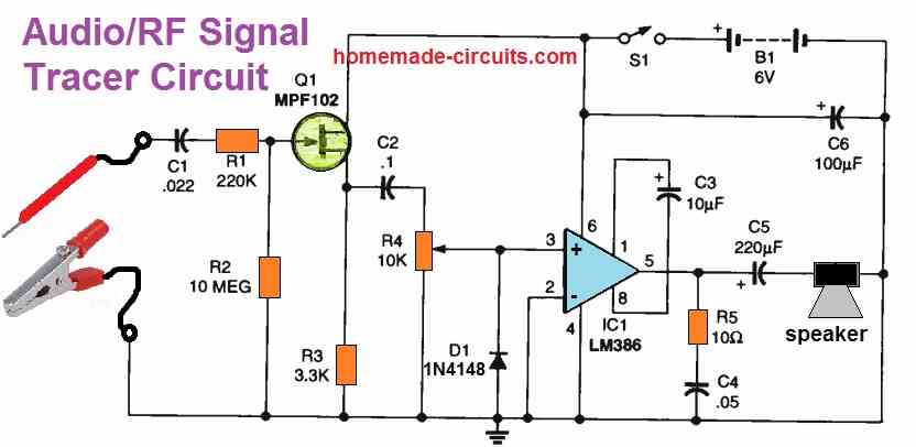
The AF/RF Signal tracer's schematic can be seen above. Q1 amplifies the input probe signal while R1 and R2 provide a bias for the FET.
R4 (the volume control) and D1 are capacitively linked to the amplified signal. Diode D1's function is to demodulate RF signals.
The signal is unaffected by D1 if you are working with audio signals. On the other hand, when dealing with RF signals, the diode behaves like a demodulator from a vintage crystal set.
The introduction of D1 increases the adaptability of the AF /RF Signal tracer. Signals that are phase-modulated or frequency-modulated (FM) or both can be detected; D1 serves as a slope detector. However, the audio quality will be substandard.
The last component of the circuit is a typical LM386 amplifier with an 8-ohm output and a gain of 200. The output of the IC LM386 may be connected to any compatible speaker or earphone.
Due to the coupling between S1 and R4, the AF/RF Signal tracer may be turned on and off by adjusting the volume, just like a battery-operated radio. A total of four AA batteries in a suitable holder serves as the power supply.
Simple Buzzer Circuit
An exact buzzer-like sound is produced by the circuit displayed below. Just a couple of ICs and a few other parts are needed to build this circuit.
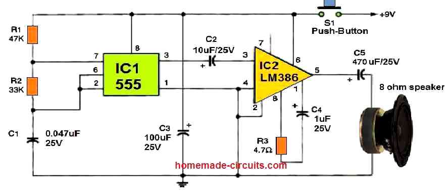
Through resistors R1 and R2, C1 begins to charge as soon as S1 is briefly pushed. In the end, it activates pin 2 of IC1's 555 oscillator/timer.
The IC subsequently starts discharging the capacitor by pushing pin 7 low via R2. As long as S1 remains pushed ON, this cycle happens repeatedly.
The pin#3 output of IC1 switches ON/OFF in response to the capacitor's charging and discharging, providing a sound frequency to IC2. IC2 is an LM386 low-voltage audio power amplifier that boosts the loudness of the tone frequency.
The sound frequency from IC1, which sounds like a genuine buzzer, is amplified by IC2 and reproduced through the speaker.
For a low-frequency buzzing sound, you can increase the value of C1 to 0.1 uF. For improved stability, you may also use a 47-F capacitor to bypass pin 7 of IC2 to ground.
Mini Megaphone Circuit
A min megaphone circuit can be built using single LM386 IC as shown in the following figure.
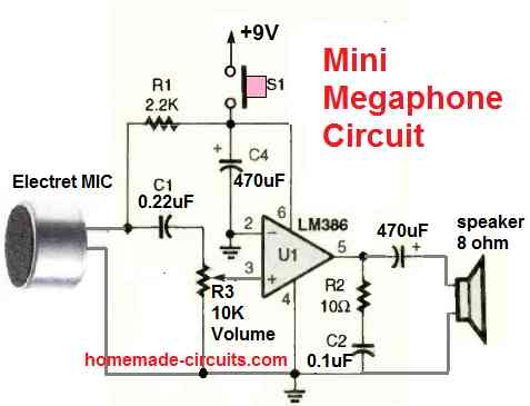
A megaphone is a hand held device with a MIC where the user can speak, so that the voice is amplified and can be listened over a larger distance.
The circuit utilizes a single LM386 IC, an electret MIC, and a small loudspeaker. It also includes a volume control pot for adjusting the loudness or the output amplification.
When the user speaks on the MIC, it is amplified through the loudspeaker allowing the user to address his or her speech loudly to the present audience.



Questions & Answers
thanks Sanatan.
sir..
how much voltage(maximum) include in this ckt..?
15 V
Can multiple num of 386 be conected in series to get greater power?
i have no idea about it so can't suggest….
Sir, i made the circuit with 5volt power from usb port. i had no 0.1uf capacitor i used 10uf capacitor. sound is very good, when i loud the sound, The speaker's voice was burst۔ what is the solution for this????? Sound should be clear on loudness.
Thankssss
Irshad, if you force the IC to work above it's specified rating then the output will distort.
so you will need to keep the input music only upto that level which does not exceed the amps max handling capacity.
Hi bro, i want to increase the outpt of LM 386 to around 5W using either Transistors or Mosfets so do have any idea how to configure the driver stage using these ????
sorry Bro, I tried but could not find any technically correct LM386 power booster circuit, most of the ideas are based on opamp instead of LM386…
Hello Sir please provide the simple mic amplifier circuit diagram and how to connect it for la 4440 audio circuit board
Thank you
Hello Raghvendra, the MIC circuit is already shown at the end of the article, you can connect the output with your LA4440
Thanks sir thanks very much and one more thing sir to ask you that please provide 250watt subwoofer audio circuit
Hi Raghavendra,
you can try the following design and add a low pass filter at the input to make it a subwoofer amp
https://www.homemade-circuits.com/make-high-power-250-watt-mosfet/
Good write up on the LM 386. One question. Can I use a transformer with the secondary connected to inputs 2 and 3 as an input device. If so could I use an 8 Ohm primary to 1300 Ohm secondary and get some extra gain?
Thank you.
Thanks Hans, I don’t think that would work, because the input of the amp is already is too sensitive and set at high gain, therefore adding more voltage at the input side would result in distortion at the output side.
I do not plan to connect pins 1 and 8 with a cap, I just wish to get rid of common mode noise. As alternative could I use a 600 Ohm:600 Ohm audio transformer connected with say 10 uF caps to 2 and 3?
Tks
OK, so you intend to transfer only the differential value to the amp and eliminate common mode noise, in that case you can try using a trafo at the input
Thank you. Would you know where to find actual schematics for a transformer input?
Tks
sorry, I do not have much idea about it.
I like this circuit, thank you. I was wondering what would be required to add headphones?
Thanks
Thank you, glad you liked it, you can simply replace the shown speaker with a headphone, just make sure to reduce the volume control suitably so that the input power does not exceed the headphone specs.
Thank you for your reply, that is easy enough.
I
respected sir,
though i can vary the gain of amplifier by varying the resistance and capacitor value between pin 1 to 8, i didn’t have an idea how actually we are getting the value of resistor and the capacitor. so if anyone can help me please..
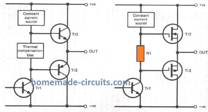
Hi Tshering, referring to the internal layout of the IC, it seems the (-)input side acts like a constant current source, and this current is replicated at the (+)input side transistors through current mirror circuit.
The addition of the capacitor allows more voltage to enter through output feedback loop to the (-)input side stage causing more current drive for the (+)input side transistor stage which in turn causes the output to become more powerful.
Could you explain why the bias cap is placed with its + side connected to pin 1 rather than to pin 8?
I’m looking at the chip’s schematic, trying to figure out why pin 1would always be more positive than pin 8 but I’m just not seeing it.
Noting that you connect it the same way in the one example you show with pin 3 grounded instead of pin 2, it would appear not to be dependent upon which of the 50k biasing resistors is shorted to ground, which at least says that it would be safe to use the same gain cap polarity with both of 2 LM386’s set up to use bridged output, one getting its input on pin 2, the other on pin 3.
What is the basis for knowing that pin 1 has a greater potential than pin 8?
Could it be as simple as balancing the sum of R3+ R4 +R5 against (R7 plus the Q8 emitter/base junction) in terms of distance from Vcc? (I wish I recognized the symbol with overlapping circles and downward arrow between Vcc and Q8’s base and wondering if it could be a clincher).
The basic function of the pin1/8 capacitor is to bypass the 1.35 k resistor. The reverse polarity of the capacitor effectively allows the current to go across the 1.35 k resistor. If the capacitor positive is connected with the pin8, the bypassing will not happen due to the capacitor charging up and blocking the current.
The circuitry associated with the input pins are mirror networks, so which pin is grounded and which is used as the input might not be too crucial, and anyway its the differential signal voltage that actual matters.
The two overlapping circles and the arrow indicate the flow of the current, according to me.
Thanks for the quick reply and refresher on electrolytics. The point of it charging up if its + side were connected to pin8 was something else I had failed to see. I guess I’ll just have to study the circuit more to figure out how pin 8 gets to be more positive than pin 1 (the opposite of what I’d initially assumed from how it gets connected).
On a related subject, would you happen to have a (hopefully not too difficult) circuit that would delay an audio signal from a microphone before feeding it to the amplifier, so that the phase of what comes out of the speaker would be delayed by a sufficient number of multiples of 360° from what the mike had picked up to prevent audio feedback? I’m trying to put a one-way intercom inside a home-made N99-equivalent respirator, so that I won’t have to keep repeating words (such as when giving my name and birthdate, at a pharmacy counter, for example) over and over until I’m understood, but I haven’t been able to satisfactorily eliminate audio feedback, even by trying to attenuate sounds above 3khz), so I was thinking perhaps introducing a delay might be a cleaner approach.
Delay line appears to be a difficult circuit, may be because I have not yet investigated and not familiar with its working….I have a couple of concepts with me, if possible I will try to publish them soon.
For the time being you can tinker with the following simple idea:
Thanks for the suggestion.
With a little research, I learned about several independently developed “generations” of dedicated bucket brigade chips. I’d finally settled on the MN3207, an easily affordable and usable NMOS BBD chip which has a maximum delay time of approximately 1/20 second and which can work with a +5V supply. The MN3007 has superior S/N and other characteristics, but using PMOS technology, it requires a negative supply, As I was researching this, I kept on studying just about every one of the “what is” and “what isn’t” conditions underlying the system and eventually discovered an unexpected mechanical basis underlying and (of course) reinforcing the feedback. I still expect to make use of these chips, only for sound effects on another project rather than for feedback prevention on this one, so thanks for steering me in the right direction.
Thanks for the valuable info, appreciate it very much!
In circuit for Bass boost , I don’t see connection between leg 1 and leg 8 ,Is it correct ? If correct can you explain for me .
many thanks
It is set with gain of 20. If you wish to increase the gain, you can add a 10uF capacitor across those pinouts
What happens if the two inputs, pins 2 & 3, are out of synch. For example, let pin 2 have a frequency of 143 hertz and pin 3 have a frequency of 135 hertz? Will the output frequency be 19,305 hertz?
The voltage levels of the two inputs will be compared by the LM386 op amp and output will be a correspondingly varying frequency.
Dear sir engineer Swagatam,
Hello. I hope you are doing fine.
I assembled your excellent 9V LM386-based circuit amplifier in order to amplify the output of a 3V melody circuit board that I had bought earlier. My plan was to use it as a door bell music generator; and it works well when I use two Nos of 9V and 3V power supplies for the “amplifier” and the “melody” circuits. However, I face a problem when I get 3V output from the 9V power supply** for the melody circuit. The melody circuit does not play any music.
** I regulated 12V output of a 220/12V transformer with LM7809 and LM7805, then reduced output of 1205 to 3V using few Nos of 1N4007 for the melody circuit.
Would you please kindly tell me if there is a solution in order to use a single ( 9V ) power supply for both circuits?
Thank you very much in advance,
Mehrdad
Thank You Dear Mehrdad, and glad you could make the project successfully.
I guess your melody circuit is a small music chip also called COB. These ICs normally have 3 terminals, one for (+) supply, one for (-) supply and one for the output. In order to make a quick 3 V supply, you can add a 3V zener diode between the (+) and the (-) terminals of the melody IC, and then connect the +9V to the (+) terminal of the IC through a 1K resistor, and connect the -9V supply with the (-) terminal of the IC. The OUT of the IC then can be connected with the input of the IC LM386.
Dear sir engineer Swagatam,
Hello. I hope you are doing fine.
Thank you so much for your very useful and comprehensive instructions. I did as you had told and the melody began playing.
Never forget your kindness Sir.
Wish you all the best and health
Mehrdad
You are most welcome Mehrdad, I am always happy to help! Please Keep up the good work!
Hi Sir Swag. hope you are glad and doing well. I have assembled a circuit as a substitution for carbon microphone to amplify the outgoing sound of an old telephone for my grand mom. It does not need to external battery at all. I sent pictures of it through Email to you.
My request is that how and which of your LM386 amplifiers could I use instead of the speaker of that carbon telephone, with no need to external battery for my very old grand mother to be able to hear it without difficulty.
Your help to an old woman is mostly appreciated and will happy her a lot dear Sir Swag.
Regards
Hi Veronika, LM386 cannot be operated without a battery or a DC supply, a minimum supply of 3V will be required to operate the IC.
Thank you Sir Swagatam for responding me. But, isn’t the voltage and ampere of the telephone line sufficient to drive your amplifier circuit based on LM386? or may be a transistor based amplifier? As you have certainly seen the circuit that I have sent to you, 2 transistors of that circuit provide their need to 5 volt electricity from telephone line. Waiting for your hopeful reply, I remain Sir. Wish you health.
Bye
Hi Veronika, if you are using telephone supply to power the LM386 then it is fine, your amplifier will work, but the supply should be within 5V and 12V DC.
Hi dear Sir Swagatam. Please do a favor and kindly describe me what is the difference of connecting R2 to pin 3 of LM386, as in your diagram ” MIC amplifier circuit using LM386 IC “, or connecting C2 to Pin 3 of LM386 that I seen on a few similar circuit diagram elsewhere.
Thanks a lot
Truly yours
Najieh
Hi Najieh, the R2 works like a volume control. A series capacitor is not required here since we already have C1 as the blocking capacitor.
Hi dear Sir Swagatam. Many thank for your prompt answer. May be I did not mean it correctly. So I beg you to please refer your Email and find the attached circuit diagram. I wanted to know what changes will occur if I substitute the place of R1 and C1 with each other. I have seem this substitution in some similar circuit diagrams.
By the way, I had forgotten my password for najieh so I created another Email named najiehsa.
Hello Najieh,
in the mic circuit if you interchange R1 with C1 it will not work.
A explained earlier, a capacitor at pin3 will be required if the audio input does not have a capacitor, but in the MIC circuit we already have C1, so no need of any additional capacitor on pin3
Hello, I’ve been working on a project that uses this circuit but I’m having issues with increasing the gain. I’ve breadboarded it and it worked fine the first time yet now adding the 10uF capacitor between pins 1 and 8 only make a very slight difference. I also noticed that putting the same capacitor between pin 1 and ground will make it very loud, which is what I want, but will that damage the LM386? Thanks.
Hello, The 10uF should cause a substantial increase in the gain of the IC, from 20 to 200, if this is not happening then something may not be right with the circuit. If the IC gets too hot then it can get damaged quickly or malfunction.
Thank you for the quick response.
I was able to solve my problem in a very unusual way. My circuit is configured with ‘V IN’ connected to pin 3 without a 10k pot. Originally, Pins 2 and 4 where connected as close together to the IC and in turn connected to ground but this doesn’t work. However, if a wire is connected across Pin 2 and 4 (and 4 to ground) that is about 16 inches long then it WILL work. Why? The resistance of the wire does not seem to matter, just length. It absolutely perplexes me.
That doesn’t look normal to me. Pin2 and pin4 are both grounded, and must be connected to ground with minimum resistance…adding a wire across these pins is not making sense…it’s difficult to understand.