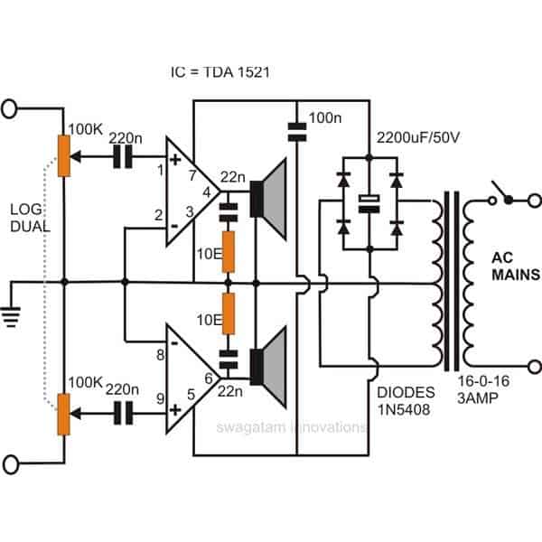
A simple stereo audio amplifier circuit discussed here is built around the IC TDA 1521, requires very few external passive components and is able to provide a powerful 12 + 12 watts of music output.
Main Features of the Stereo Amplifier IC
The IC contains all the built in features required for an amplifier circuit like automatic mute, overload and over heat protections.
The circuit of a stereo audio amplifier using IC TDA 1521 presented here is very simple to build, utilizes very few external components and yet is able to produce 12 + 12 watts of hi-fi music power.
The input can be from a CD player or your cell phone. Building a stereo audio amplifier usually refers to using two mono amplifiers and integrating their inputs, common ground and the supply to get the required stereo provisions.
However such circuits generally tend to become too bulky and moreover making identical modules simply makes everything double and thus the costs involved also get doubled.
But there are quite a few single chips available in the market which contains built-in dual amplifier blocks to make things really compact and sleek.
One such IC is the TDA1521 which is a dual high fidelity power amplifier chip embedded inside a 9-pin plastic encapsulation.
The chip is perfectly suited to be used with rough power supplies and indeed has rugged specifications.
How to Build the Amplifier Circuit
We will discuss how to make a simple stereo amplifier using this IC, but before that let’s first go through some interesting specifications of this device.
The TDA1521 basically produces optimum performance with dual supply voltages of around 16 volts and will deliver a good 2 to 12 watts of music thrust into a couple of 8 Ohms loud speakers.
The gain of the amplifier is internally calibrated and fixed at 30 dB with a space of 0.2 dB. This ensures a nice balance of gain in between its two channels.
The chip carries a special in-built music mute facility. The feature enables the IC to disconnect its non-inverting inputs when the supply falls below +/- 6 volts, although the amplifier remains successfully biased at this voltage.
The above property makes the circuit free from unnecessary clicking noises while switching the circuit ON and OFF.
Short Circuit and Overload Protection
The output of the IC is well protected against overloads and accidental short circuits.
The IC also includes a thermal runaway protection so that excessive heating of the IC will not damage it; however it may shut-off at high case temperatures.
Therefore it is recommended that the IC is fixed with a heatsink rated at 4K/W when the output is subjected to a 8 Ohm load @ +/- 16 volts supply.
Please note that the pin #5 of the IC is internally linked with the external metal tab over the IC.
Parts List
- Resistors are 1/4 watt 5% CFR
- 10 Ω = 2
- Potentiometer 100 k = 2
- Capacitors are PPC 100 V, unless specified.
- 220 nF = 2
- 22 nF = 2
- 100 nF = 1
- Electrolytic 2200 µF / 50 V = 1
- Bridge rectifier diodes 1N5402 = 4
- Transformer 16-0-16V 3 amp = 1
- Loudspeaker 20 watts 8 ohm = 2
Technical Specifications
The following data provides a few interesting specifications accompanied with this stereo amplifier chip:
- Total Harmonic Distortion: 0.5% @ 12 watts,
- Quiscent Current Drain is less than 40 mA,
- Gain Balance is around 0.2 dB,
- Supply Ripple Rejection is around 60 dB,
- Channel Separation is @ 70 dB,
- Output Offset Voltage is 20 mV,
- Power Bandwidth (@3 dB) is 20 to 20000 Hz.
Circuit Operation:
The stereo amplifier circuit shown is quite simple and is almost self explanatory.
As you can see this stereo audio amplifier hardly requires any components to become a full fledged stereo amplifier.
Just a resistor/ capacitor network to handle frequency compensation and a couple of input DC blocking capacitors is all that is needed to generate high quality stereo music from this little package….amazing indeed.
The whole unit of this stereo audio amplifier can be easily built over a general purpose board and the whole system along with the power supply may be enclosed inside a sturdy metallic box.
Whether it’s your CD player or your cell phone, it will convert every bit of it into a heart throbbing true pulsating stereo output.


Comments
Bonjour monsieur.
J’ai monté ça avec une alimentation de +15V et -15V . Ça fait beaucoup de bruit et de ronflement. La source de tension est bien filtrée. Et j’ai fait bien le montage à plusieurs reprises
Hello Daouda,
You can reduce the humming noise by using a large electrolytic capacitor such as a 68000uF / 50V.
And make sure to use a metallic box as the enclosure and clamp the transformer tightly with the metallic box, ad connect the Ground line of the power supply with the metallic box.
Oh, and I just found my answer, that “10E’ means “10 ohms”.
Sir,
When examining thus circuit, I see two components between two capacitors Going from speakers input, and pins 4 & 6 of the IC, are two components, as I said labeled “10E” . So what components are these? Or was this a misprint and should be labeled as “10R”?
And a possible answer to the writer named Arun from October 24 2017, if he would run the returns from the front left and right speakers to the center amp, and the return from the center amp to ground, and the outputs from the center amp to the center driver, that may resolve his problem. Or just not use a center amp, and wire the returns from both the front left and right signals to the one side of the center speaker and the other center terminal to ground. Asumming that there is still a problem.
Hi Owen, as you rightly realized,the R and E are sometimes used as an alternate term for indicating the OHM symbol.
I hope Mr. Arun will read your suggestion and find it useful.
Sir I want to make a 5.1 hometheatre setup in my small room. I already have a Mackie professional studio monitor speaker pair currently using as stereo speakers. I have a Dolby 5.1 decoder audio gear which can create 5.1 tracks from any encoded Dolby audio track. So what I am planning is to buy a good quality 2.1 speaker system with powerfull bass and use the satellite speakers of it as Surround speakers in my new 5.1 system.. So a total of 5 speakers ( Front Left, Front Right, Left Surround, Right Surround and subwoofer ) will be there… The Centre channel is then missing… What I am thinking is Use the Front Left and Right Speakers together to create the centre channel effect as it is a studio quality one it can deliver good quality dialogues also…
Now the problem is ; my 5.1 decoder gear is having 6 outputs ( FL, FR, C,LS,RS ans SUB ).. how can I feed the signals to the Front left and right speakers to create the soundscapes of Front Left, Front Right together with Centre channel ? The left speaker has to feed the FL signal along with the Centre channel signal similiary the Right one FR signal with centre channel signal… My question is – Is it possible to feed each speakers ( FL, FR ) with the combination of the corresponding complex analog sound signal ? Is there any way for it without overloading or affecting each channel output from the 5.1 decoder gear ?
I’m a sorry Arun, I have no clues regarding this, hopefully somebody else in this forum would be able to suggest something useful..
Hello sir i want an amplifier for my cR which vmcan work on 12v single power supply and atleast 30w power
is it possible to parallel transistors in this circuit I sent to get more power out say 600 watts, what would I need to do?
https://www.dropbox.com/s/epye1zn0c0hhkwu/200watt-anfi-devre-semasi.png?dl=0
the image is taking too long to open…
Ok sorry about that this is my google drive link
https://drive.google.com/file/d/0B0N-CQJdWSP0RXBIWHZpclRRVEk/view?usp=sharing
I am not sure whether the transistor can be paralleled in this circuit or not, normally transistors can be paralleled to increase power by using individual resistors at their bases, but in this deign I am not sure because of the IC in the middle.
the Ic in this article uses ± 21 V maximum would that be 42 volts accross the 2 end termials and 21v from end to center? Or is it that ± 21V is 10.5v from end terminal to center?
it's 42V from end to end
Well thnx , but now we are given an amplifier circuit from the net. Its a 20w stereo amplifier using tda7377. They have also used an irf1405 mosfet …. but I dont know why it has been used. I am not getting the irf1405 mosfet anywhere in the market….. what should I do?? Is there any other mosfet which I can use over there? Can u tell me what is the mosfet used as….. a voltage regulator or linear amplifier? Is there any alternative?
Thanks in advance. Regards.
check the datasheet of the mosfet to find its voltage and current specs, any other mosfet with similar rating can be used as a replacement.
without seeing the diagram I won't be able to suggest much.
How do i add bass and treble control in the circuit?
You can do it as explained here:
https://www.homemade-circuits.com/2012/01/how-to-make-your-own-active.html
Hi sir i am new to electronics. We are asked to make a battery operated dual audio amplifier for MOBILE PHONES in OUR electronic project. The above circuit is fine except that it uses mains supply and a transformer. Please suggest a good circuit with ALL POSSIBLE DETAILS AS I AM NEW TO ALL THIS. Thanks in advance.
…sorry it's pin5 of the IC ….not the battery.
Hi Kanak,
you can operate the above circuit with a battery as well, however you will need two 12V batteries and connect them in series.
just remove the four diode bridge and the capacitor and the transformer and connect the battery as I have explained below:
The center series connection of the two batteries will join with the line which is marked with a "ground" symbol.
positive of the battrey will go to the pin7 of the IC and negative with pin5 of the battrey
hellow sir . i am new to electronics and i have been interested in amplifiers projects which they have been working well . But i have been facing problem of signal clipping mostly on small amplifiers such as tda 2822 even of higher such as tda2040 . how can i avoid this
Hello Joshua, are you sure it's signal clipping? Did you check it with an oscilloscope?
TDA2030 will not have this problem normally, please confirm the fault once again….
Pls sir, help me with this questions:
1. Are all capacitor electrolytic?
2. Are those 100k presets?
3. Is there volume control in the circuit?
4. What is 10E and log dual.
Thanks alot.
1. the one which is between bridge is only electrolytic erst all are ceramic disc.
2. 100K are pots not presets.
3. the 100k pots are the volume controls.
4. 10E = 10 ohms, log is the specification of the pots.
thanks for the reply
no it says here:
Impedance: 4 ohms
Rated Input: 1.6 watts
made in japan
and its a casio product. A speaker from my mother's piano. :- )
I have another question.
1. Can I power the speaker (mentioned above) with 10 watts amplifier?
I think you should use a smaller amplifier with this speaker,10 watts could damage it, you can try a LM386 circuit for it.
good evening sir!!!
belated christmas and a happy new year!!
I have some doubts.
1. Do I need to use preamplifier before the amplifier?
2. Can I use 4w / 1.6 ohms Speaker?
wish you the same
1)no need of a preamp if the input is from a source such as a cellphone, DVD player, TV, Ipod etc.
2) did you mean 16 ohms? never heard of 4 watt 1.6 ohms speaker, anyway both can be used here.