• Skip to main content
  • Skip to primary sidebar

Homemade Circuit Projects

Need circuit help? Post them in the comments! I've answered over 50,000!

Blog | Categories | About | Hire Me | Contact | Calculators-online
You are here: Home / Datasheets and Components / Cree XLamp XM-L LED Datasheet

Cree XLamp XM-L LED Datasheet

Last Updated on May 17, 2026 by Swagatam 12 Comments

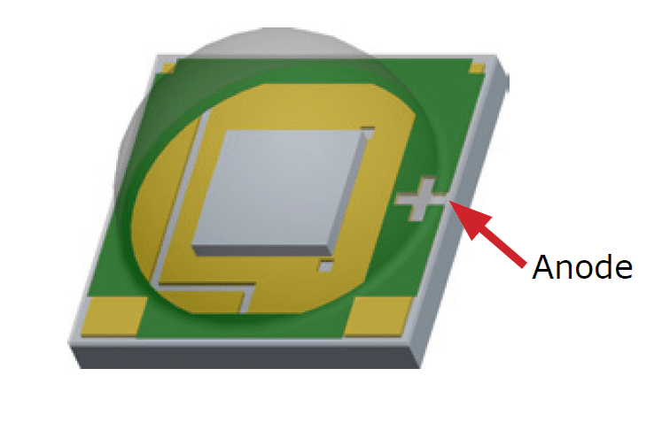
The XLamp XM-LED can be considered as the highest performing, single die solid state LED module which is able to produce lights at ultra bright intensities. I have explained it's datasheet, specifications.

Table of Contents
  • High Illumination Efficacy
    • Main Electrical Specifications
    • How to Drive a Cree Xlamp XM-LED
    • Applying In Automotive Headlights.
    • For Home Lighting

High Illumination Efficacy

Due to it's ultra bright and high efficiency values, the Xlamp becomes highly suitable for applications such as in automotive headlamps, stadium flood lights, for home lighting, street lighting, practically anywhere which requires high illumination at minimum space and consumption.

To be precise an Xlamp is able to generate 1000 lumen with 100 lumen per watt efficacy.

The main features which makes this breakthrough device exceptionally desirable for lighting applications may be studied with the following data:

Main Electrical Specifications

  1. Operating current: 3000 mA or 3 Amps
  2. Operating Voltage: 3.3V
  3. Low thermal resistance: 2.5 °C/W
  4. Maximum junction temperature: 150 °C
  5. Viewing angle: 125°
  6. Available in cool white, 80‑CRIminimum neutral white and 80‑CRI, 85‑CRI and 90‑CRI warm white
  7. ANSI‑compatible chromaticity bins
  8. Infinite Store life at ≤ 30 ºC/85% RH
  9. Re flow solderable - JEDEC J‑STD‑020C
  10. Electrically neutral thermal path
  11. RoHS- and REACh‑compliant
  12. UL-recognized component (E349212)

How to Drive a Cree Xlamp XM-LED

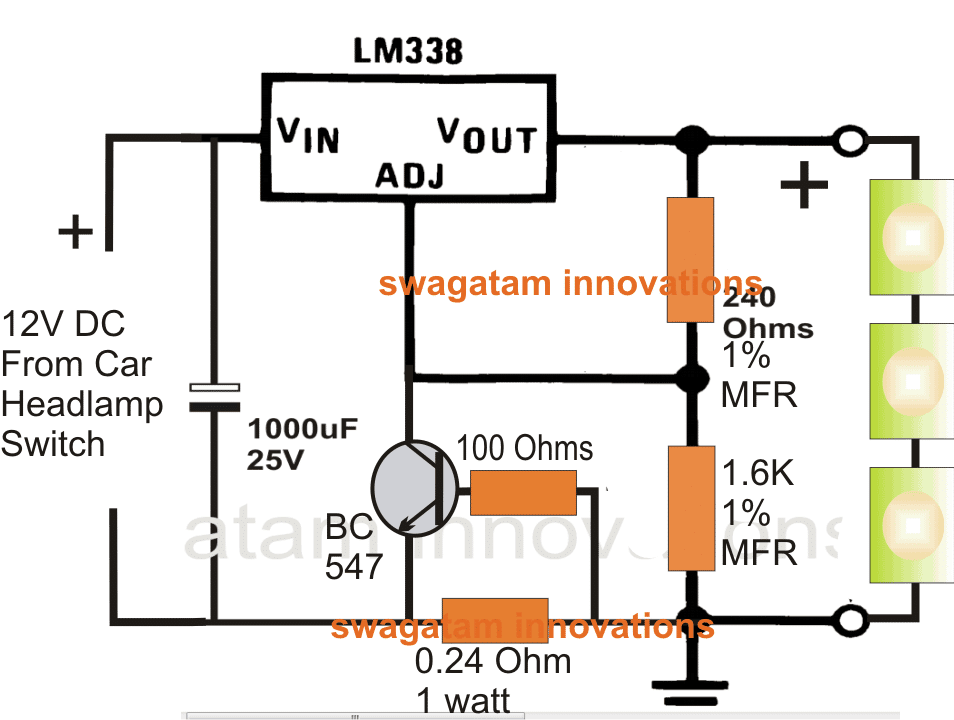
Since the the performance and life of the Cree Xlamp is inversely proportional to its junction temperature, a high quality current controlled driver becomes a must for operating these ultra bright LEDs. I have explained a few of the application circuits for safely driving  the proposed LED devices.

Applying In Automotive Headlights.

When used for automotive headlamp applications, the following circuit may be employed:
For Home Lighting

The same circuit may be used  for home lighting applications, the design is given below:
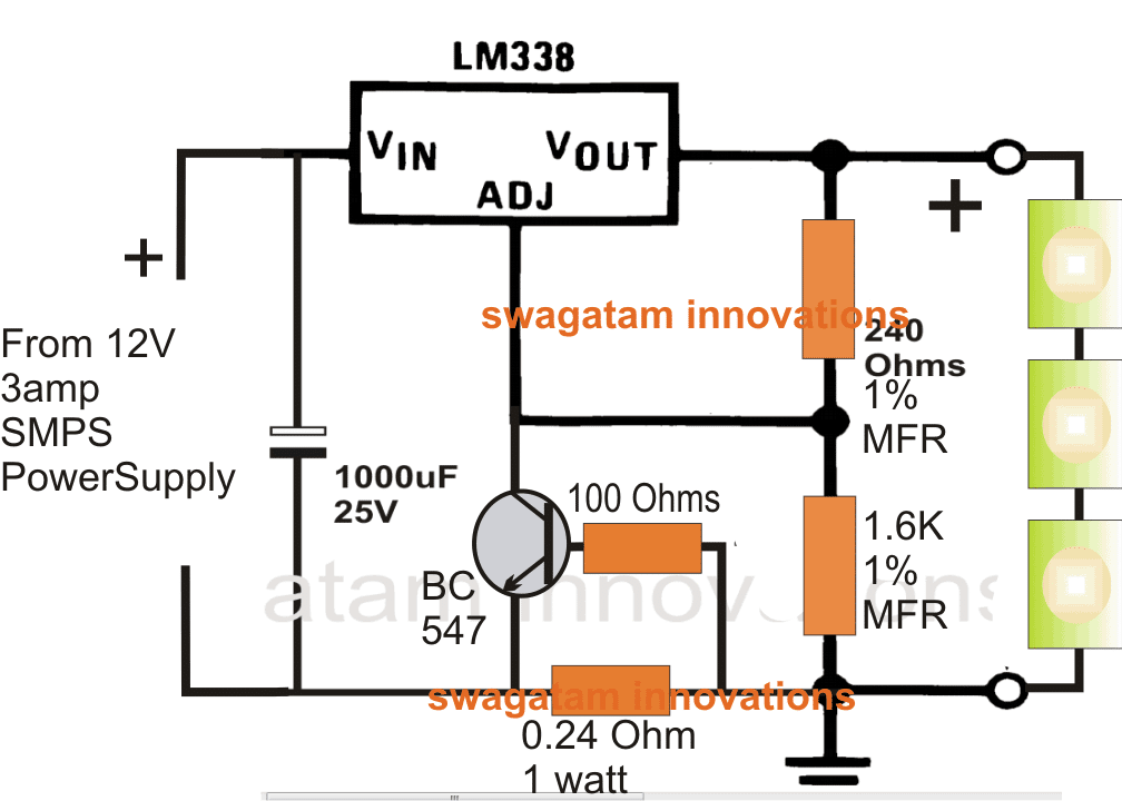
For all applications, the LEDs must be mounted on suitable heatsinks for getting optimal performance.

For more info on this, you may refer to the original datasheet

You'll also like:

  • IC 4043 dtasheet pinoutUnderstanding IC 4043B, IC 4044B CMOS Quad 3-State R/S Latch – Working and Pinouts
  • IC 4001 Datasheet, Pinout, Applications
  • voltage regulator using IC 741Op amp IC 741 Datasheet, Pinout, Applications
  • standardresistorvaluesStandard Resistor E-series Values

Filed Under: Datasheets and Components Tagged With: Cree, Datasheet, LED, XLamp, XM

About Swagatam

I am an electronics engineer and doing practical hands-on work from more than 15 years now. Building real circuits, testing them and also making PCB layouts by myself. I really love doing all these things like inventing something new, designing electronics and also helping other people like hobby guys who want to make their own cool circuits at home.

And that is the main reason why I started this website homemade-circuits.com, to share different types of circuit ideas..

If you are having any kind of doubt or question related to circuits then just write down your question in the comment box below, I am like always checking, so I guarantee I will reply you for sure!


Previous Post: « Car Head Lamp Fader Circuit (Breathing Effect Generator)
Next Post: 55V 110A N-Channel Mosfet IRF3205 Datasheet »

Reader Interactions

Questions & Answers

Total Posts: 12
Newest Oldest
ABDULLAH
May 18, 2018 • 8 years ago #60563

sir, i want to use a single 5w cree XML led for automotive …
what will be circuit for that

Reply
SwagatamAdmin
May 18, 2018 • 8 years ago #60573

Abdullah,

you can attach any desired LED through an appropriate current limiter stage as explained in the following article:

https://www.homemade-circuits.com/universal-high-watt-led-current-limiter/

Reply
Swaroop K
August 6, 2015 • 11 years ago #32904

Hi, is this circuit can be used for automotive headlight purpose where input volt with be 12~15v. Also can we able to connect Cree XML T6 10w led X 3 Nos? and what will be the output Amp.

Reply
SwagatamAdmin
August 7, 2015 • 11 years ago #32930

output amp will be 10/12 = 0.83 amps

Reply
SwagatamAdmin
August 7, 2015 • 11 years ago #32929

yes it can be used for automotive headlight purpose.

3 x 10 watt can be used with the above shown circuits, make sure to calculate the 0.24 resistor accordingly

Reply
SwagatamAdmin
August 27, 2013 • 13 years ago #14648

The 1% resistors can be 1/4 watt types while the 0.24 ohm resistor is 1 watt, wire-wound type.

Reply
mubarak
July 23, 2013 • 13 years ago #13694

thanyou very mach

Reply
SwagatamAdmin
July 23, 2013 • 13 years ago #13680

1amp, 500v thermistor will do the job..

Reply
SwagatamAdmin
July 23, 2013 • 13 years ago #13666

you can use 105/400v as the capacitor but include a thermister at the input to prevent LED damage and blackening.

Reply
mubarak
July 22, 2013 • 13 years ago #13659

which rate of thermistor use for this circuit.474 use after 8 mm led light not enough and it take 19mA when i use 105 it take 39mA .also 56 ohm resister i will use metal oxide type.why led middle came a black point? p[lease explain me to this problem

Reply
SwagatamAdmin
July 22, 2013 • 13 years ago #13636

use 474/400v capacitor in place of 105, and connect a thermistor at the input. The thermistor explanation can be found here:

https://www.homemade-circuits.com/2013/02/using-ntc-resistor-as-surge-suppressor.html

Reply
mubarak
July 21, 2013 • 13 years ago #13619

sir i will made 230v led bulb 8mm 0.5w 55 led for each circuit .when i make this bulb starting give good bright light ,after 2 or 3 month it loss 40 percent light and led chip middle have black point.why loss light of this led please inform to me what the wrong of this circuit
i use following parts of this circuit
105 capacitor mylor
56 ohm 1w resister
22uf capacitor and 890k,560 k resister 0,25w
4 pcs diode

Reply

Need Help? Please Leave a Comment! We value your input—Kindly keep it relevant to the above topic! Cancel reply

Your email address will not be published. Required fields are marked *

Primary Sidebar


My Youtube Channel

Circuit Simulator

circuit simulator image


Subscribe to get New Circuits in your Email


Categories

  • Arduino Projects (95)
  • Audio and Amplifier Projects (134)
  • Automation Projects (18)
  • Automobile Electronics (103)
  • Battery Charger Circuits (88)
  • Datasheets and Components (109)
  • Electronics Theory (149)
  • Energy from Magnets and Earth (40)
  • Games and Sports Projects (11)
  • Grid and 3-Phase (20)
  • Health related Projects (27)
  • Home Electrical Circuits (13)
  • Indicator Circuits (16)
  • Inverter Circuits (100)
  • Lamps and Lights (162)
  • Meters and Testers (72)
  • Mini Projects (28)
  • Motor Controller (68)
  • Oscillator Circuits (28)
  • Pets and Pests (15)
  • Power Supply Circuits (91)
  • Remote Control Circuits (50)
  • Security and Alarm (65)
  • Sensors and Detectors (107)
  • SMPS and Converters (45)
  • Solar Controller Circuits (61)
  • Temperature Controllers (43)
  • Timer and Delay Relay (50)
  • Voltage Control and Protection (44)
  • Water Controller (37)
  • Wireless Circuits (31)


Other Links

  • Privacy Policy
  • Cookie Policy
  • Disclaimer
  • Copyright
  • Videos
  • Sitemap

People also Search

555 Circuits | 741 Circuits | LM324 Circuits | LM338 Circuits | 4017 Circuits | Ultrasonic Projects | SMPS Projects | Christmas Projects | MOSFETs | Radio Circuits | Laser Circuits | PIR Projects |


Recent Comments

  • Swagatam on DPDT Relay Working, Pinouts, Testing Explained
  • Swagatam on DPDT Relay Working, Pinouts, Testing Explained
  • Swagatam on Inverter LC Filter Calculator
  • Swagatam on Notch Filter Circuits with Design Details
  • Nare Mashiachidi on DPDT Relay Working, Pinouts, Testing Explained

Social Profiles

  • Twitter
  • YouTube
  • Instagram
  • Pinterest
  • My Facebook-Page
  • Stack Exchange
  • Linkedin

© 2026 · Swagatam Innovations