In this post I will show how to construct a password security lock circuit, which can be accessed by a 6-digit password. To be more precise it is alpha numeric password.
Hardware for this Project
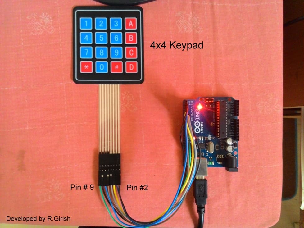
We are going to utilize 4x4 keypad, which consists of 0 to 9 decimal values, two special character ‘#’ and ‘*’ and A to D alphabets. The combination of these characters can be used as password.
The Arduino is the brain of the system, a relay is interfaced with Arduino to activate and deactivate, when the correct password is commanded. Two indicator LED is utilized here to indicate status of the lock system.
If you are not familiar with 4x4 keypad, please refer to my earlier article, which comprehensively discussed basics of 4x4 matrix keypad
The proposed project has pretty minimalistic hardware design. It just consist a keypad, relay, arduino and couple of LEDs, even a noob in arduino can accomplish it with ease.
The only part which is slightly difficult in this project is the coding, need not to worry the code is given in this project. The program should be written in such a way that, it is fool proof and no hijacker can hack the system.
But, be careful if you expose the hardware or the hardware of this project is easily accessible, the relay can be hacked with ease. So keep this project in well protected chassis.
How it Works
Note: A current limiting resistor 4.7K must be connected to base of the transistor, which is not shown in the diagram.
Now let’s see how this Arduino password security lock circuit functions, please read the instruction given below carefully, in order to operate the circuit.
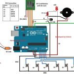
Circuit Diagram
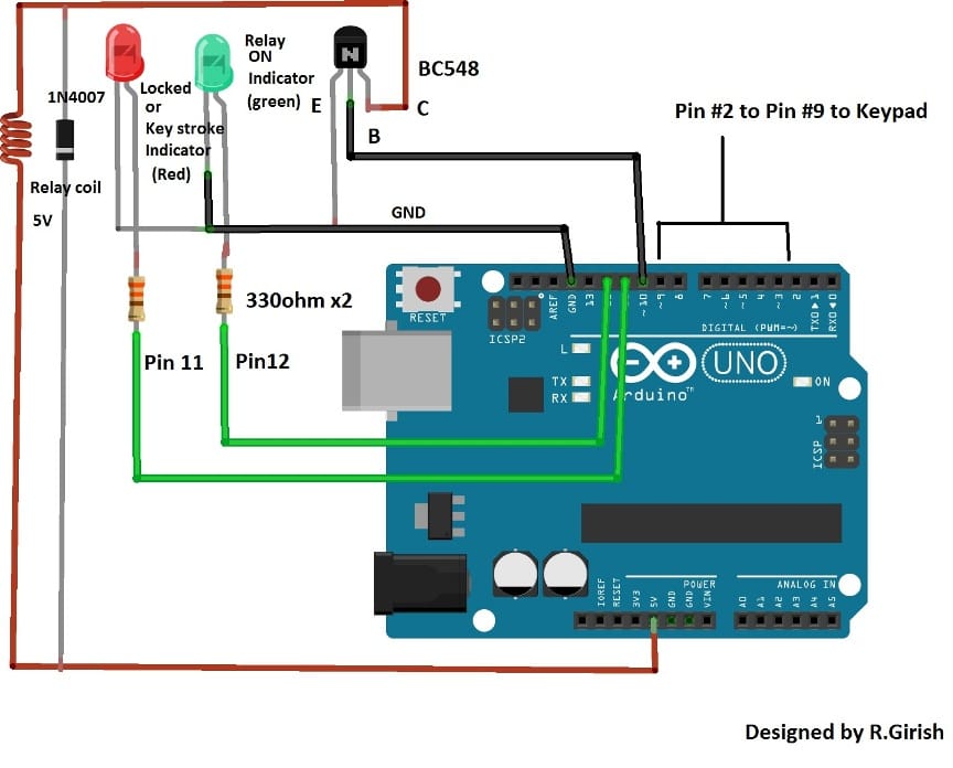
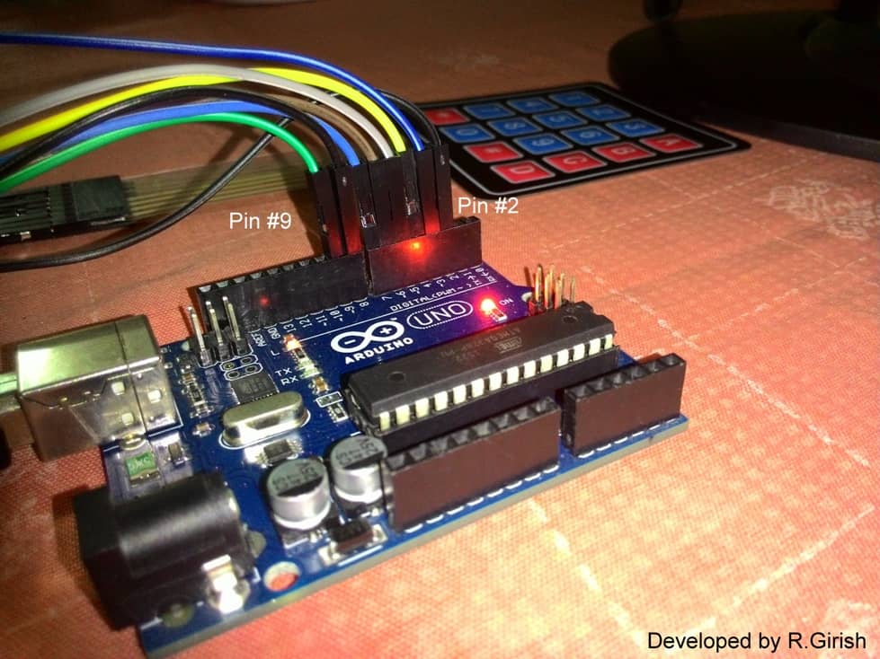
Here are the two illustrations how to interface keyboard and Arduino:
• When the circuit is powered on, it asks for password, you can see on the serial monitor (serial monitor is not mandatory but, can be used for testing purpose).
• Enter the password which you entered in the program before compiling it.
• While you press the keys, green LED blinks for one tenth of a second, indicating that some key is pressed by the user.
• Once you entered the 6-digit password, press ‘D’ in the keypad which acts as ‘Enter’. If your password is correct, the relay gets activated, green LED turns ON.
• To deactivate the relay, press ‘C’ in the keypad. When, this is done, green LED turns OFF and relay gets deactivated. No other key can deactivate the relay.
• If the password enter by the user is incorrect, then red LED lights up and the user have to wait 30 second to enter the next attempt. When the 30 second is over, the red LED turns OFF, informing the user that, the system ready to get input from the user.
• When the relay is deactivated after successful activation, in order to activate the relay again, the user needs to enter the password again and press ‘D’.
Here is a special case:
• When the correct password is entered, the relay gets activated and after the successful deactivation, when the user hits any one wrong keystroke (not whole password), the program recognize as incorrect password and the user need to wait another 30 second. If this was a hijacker it will delay the number of attempt done by the hijacker.
• When correct keystroke is pressed on the first attempt, only then it allows to enter next key. This is only for first keystroke only and not for all the successive keystrokes.
• The motto of the above explained concept is to delay the number of attempts done by the hijacker.
Program Code:
//--------------------------------- Program Developed by R.Girish --------------------------//
#include <Keypad.h>

/* ---------------- Keypad configuration ---------------- */
const byte ROWS = 4;
const byte COLS = 4;

/* 6-character password (fixed length) */
char pass[] = "123ABC";

/* Output pins */
int OP = 10;        // Relay output
int green = 12;     // Green LED
int red = 11;       // Red LED

/* Key variables */
char key1, key2, key3, key4, key5, key6;
char dumpkey;
char keyOK;
char offkey;

/* Control keys */
char ok[] = "D";    // Enter / OK key
char off[] = "C";   // OFF key

/* Progress counter */
int z = 0;

/* Keypad layout */
char keys[ROWS][COLS] =
{
  {'D', '#', '0', '*'},
  {'C', '9', '8', '7'},
  {'B', '6', '5', '4'},
  {'A', '3', '2', '1'}
};

/* Keypad pin connections */
byte rowPins[ROWS] = {6, 7, 8, 9};   // Row pins
byte colPins[COLS] = {2, 3, 4, 5};   // Column pins

/* Initialize keypad */
Keypad keypad = Keypad(makeKeymap(keys), rowPins, colPins, ROWS, COLS);

/* ---------------- Setup ---------------- */
void setup()
{
  Serial.begin(9600);

  pinMode(OP, OUTPUT);
  pinMode(green, OUTPUT);
  pinMode(red, OUTPUT);

  digitalWrite(OP, LOW);   // Relay OFF initially
}

/* ---------------- Main loop ---------------- */
void loop()
{
top:
  z = 0;   // Reset progress counter

  Serial.println();
  Serial.println("[Press D = Enter]");
  Serial.print("Enter the password: ");

  /* -------- First digit -------- */
  key1 = keypad.waitForKey();
  if (key1 == pass[0])
  {
    digitalWrite(green, HIGH);
    delay(100);
    digitalWrite(green, LOW);
    z = 1;
    Serial.print("*");
    goto A;
  }
  else goto dump;

A:
  key2 = keypad.waitForKey();
  if (key2 == pass[1])
  {
    digitalWrite(green, HIGH);
    delay(100);
    digitalWrite(green, LOW);
    z = 2;
    Serial.print("*");
    goto B;
  }
  else goto dump;

B:
  key3 = keypad.waitForKey();
  if (key3 == pass[2])
  {
    digitalWrite(green, HIGH);
    delay(100);
    digitalWrite(green, LOW);
    z = 3;
    Serial.print("*");
    goto C;
  }
  else goto dump;

C:
  key4 = keypad.waitForKey();
  if (key4 == pass[3])
  {
    digitalWrite(green, HIGH);
    delay(100);
    digitalWrite(green, LOW);
    z = 4;
    Serial.print("*");
    goto D;
  }
  else goto dump;

D:
  key5 = keypad.waitForKey();
  if (key5 == pass[4])
  {
    digitalWrite(green, HIGH);
    delay(100);
    digitalWrite(green, LOW);
    z = 5;
    Serial.print("*");
    goto E;
  }
  else goto dump;

E:
  key6 = keypad.waitForKey();
  if (key6 == pass[5])
  {
    digitalWrite(green, HIGH);
    delay(100);
    digitalWrite(green, LOW);
    z = 6;
    Serial.print("*");
    goto ok;
  }
  else goto dump;

/* -------- Password correct -------- */
ok:
  keyOK = keypad.waitForKey();
  if (keyOK == ok[0])
  {
    digitalWrite(OP, HIGH);     // Relay ON
    digitalWrite(green, HIGH);
    Serial.println();
    Serial.println("Relay Activated, Press 'C' to Deactivate.");
    goto off;
  }
  else
  {
    Serial.println();
    Serial.println("Press 'D' to Enter");
    goto ok;
  }

/* -------- Turn OFF relay -------- */
off:
  offkey = keypad.waitForKey();
  if (offkey == off[0])
  {
    digitalWrite(OP, LOW);
    digitalWrite(green, LOW);
    Serial.println("Relay Deactivated.");
    goto top;
  }
  else
  {
    Serial.println("Press 'C' to Deactivate");
    goto off;
  }

/* -------- Dump remaining keys if wrong -------- */
dump:
  digitalWrite(green, HIGH);
  delay(100);
  digitalWrite(green, LOW);

  while (z < 6)
  {
    Serial.print("*");
    dumpkey = keypad.waitForKey();
    z++;
  }

  goto error;

/* -------- Error lockout -------- */
error:
  Serial.println();
  Serial.print("Wrong password, Wait for 30 seconds.");

  digitalWrite(red, HIGH);
  delay(10000);
  delay(10000);
  delay(10000);
  digitalWrite(red, LOW);

  goto top;
}
//--------------------------------- Program Developed by R.Girish --------------------------//
NOTE: To set password: char pass[] = "123ABC"; // 6 digit password only (no less or no more)
Change “123ABC” with your own password, inside quotation mark.
Make sure the password set in the program is 6-digit ONLY, no less or no more but, exactly 6-digit. Otherwise the program won’t function correctly.
If you have any further doubts regarding the explained password security lock circuit, please feel free to post them through your comments


Questions & Answers
sir can i use this circuit for car ignition if not kindly suggest a circuit so its helpful thank you sir
Satish, yes you an use this circuit for car ignition locking or for any relevant locking application
Dear Swagatam,I am interested to learn
Arduino.But I am novice so please post some links whether I can learn ABCD of
Arduino.
Dear Manas, you can refer to the following link
https://www.arduino.cc/en/Tutorial/HomePage
so huge , i like that its massive