• Skip to main content
  • Skip to primary sidebar

Homemade Circuit Projects

Need circuit help? Post them in the comments! I've answered over 50,000!

Blog | Categories | About | Contact | Calculators-online
You are here: Home / Sensors and Detectors / Microwave Sensor or a Doppler Sensor Circuit

Microwave Sensor or a Doppler Sensor Circuit

Last Updated on June 23, 2019 by Swagatam 5 Comments

In this article we study the microwave sensor IC KMY 24 and try to understand its main features and its pinout implementation details.

How Doppler Sensor KMY24 Works

The KMY24 microwave sensor module is designed and built on the concept of Doppler effect. When correctly configured it radiates a low power microwave signal of around 2.45 GHz across the directed zone.

When an object (target) that could be even a human being, comes in the range of the emitted signal, the signals get reflected back to the sensor module with some disturbance relative to the original frequency, this is popularly known as the Doppler shift.
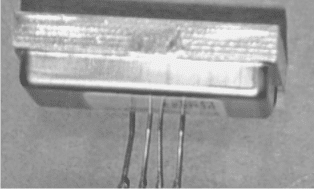
KMY 24 Microwave Sensor Pinout View
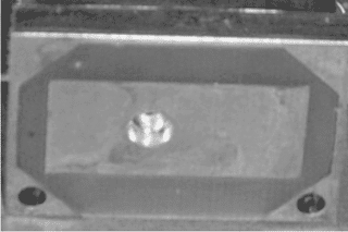
KMY 24 Microwave Sensor Front View

Once this reflected frequency shift is detected by the sensor, the in built circuitry instantly mixes the reflected frequency with the existing original frequency and produces two individual frequencies across its specified outputs.

What's Doppler Effect

As per the principles of Doppler effect this frequency phase shift could be either positive or negative depending upon whether the object in the sensor zone was receding or approaching the sensor.

The function of the KMY24 concludes here, and the outputs from the device now needs to be amplified through suitable voltage amplifier configuration, for example through an differential opamp amplifier circuit etc.

Further on the opamp output may be appropriately terminated with a relay stage or a recorder or an alarm for distinguishing or identifying the sensed parameters.

Technical Features of the IC

The main features of the IC KMY24 may be learned as follows:

  • High sensitivity and detection even when a relatively smaller target approaches the zone.
  • Twin mixer circuitry for enabling directional movement detection of the target
  • High reliability for achieving fool proof results
  • Meager power consumption making it perfectly suitable for battery operated applications.
  • Minimal harmonic emission for reduced RF disturbance in the atmosphere.
  • Compact size.

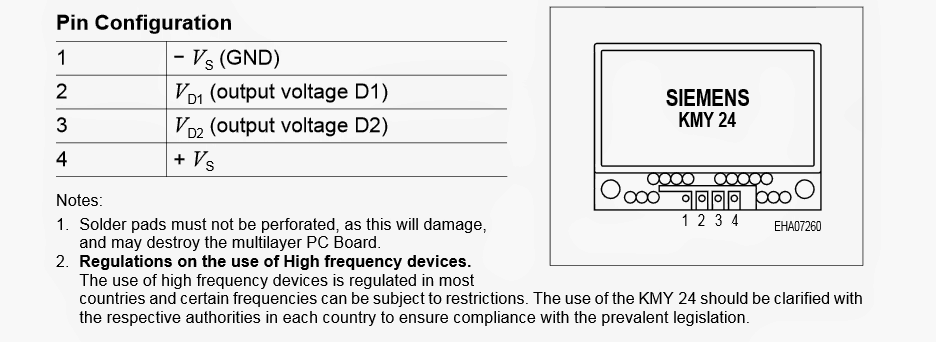
The following image shows the pinout details of the KMY 24 microwave sensor

Pinout Detail of the Microwave Sensor IC
KMY2B242Bpinouts

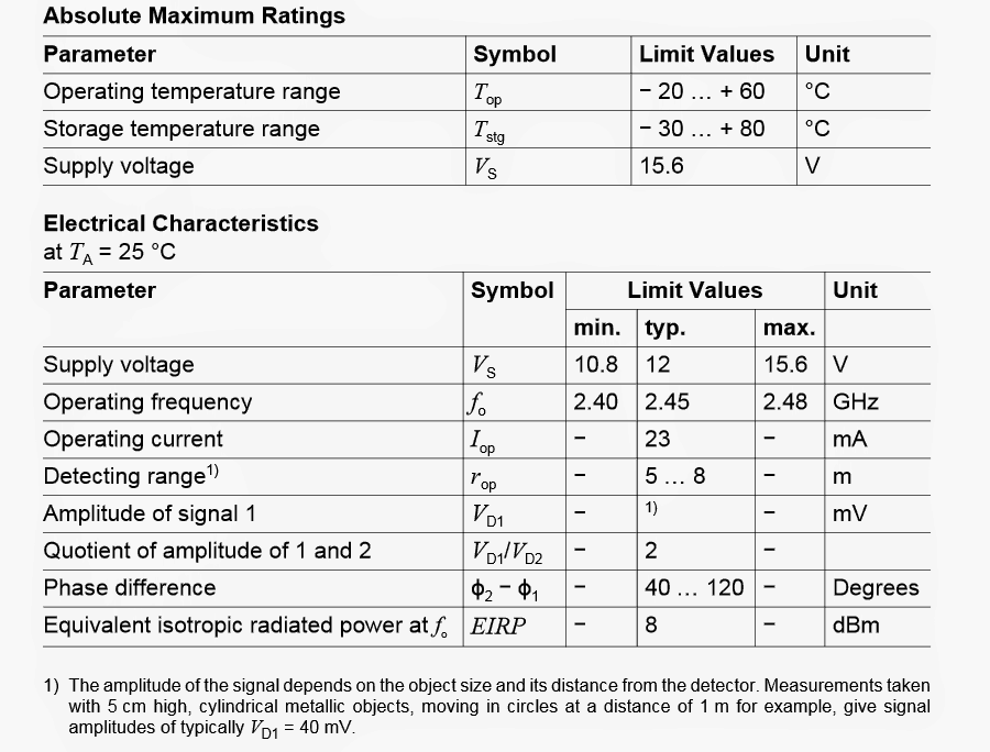
The next image provides the breakdown parameters or the absolute maximum voltage and current ratings that must be applied to the IC, these parameters must not be exceeded, to be precise these must be kept well below the shown values.

Maximum Electrical Tolerance Specs
kmy 2

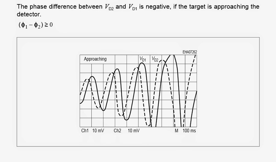
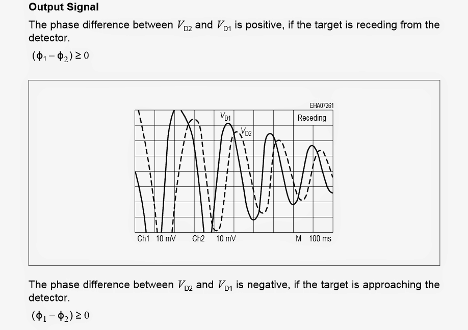
The two images shown below depict the phase shift or the difference in the position of the reflected frequency relative to the original radiated frequency when the target is approaching (first image below), and when the target is receding or going back (the second diagram below).

Analyzing Phase Shift Difference
output2Breceding
target2Bapproaching

In the next (upcoming) article we'll try to understand regarding how to use a microwave sensor through a practical circuit.

You'll also like:

  • 1.  How to Make a Transformer Winding Counter Circuit
  • 2.  Simple Mobile Phone Detector Circuit [Tested]
  • 3.  Obstacle Avoiding Robot Circuit without Microcontroller
  • 4.  Impact Collision Switch Sensor Module and Circuit Diagram
  • 5.  Alcohol Detector Meter Circuit using MQ-3 Sensor Module
  • 6.  Simple Shadow Sensor Alarm Circuit

About Swagatam

I am an electronics engineer with over 15 years of hands-on experience. I am passionate about inventing, designing electronic circuits and PCBs, and helping hobbyists bring their projects to life. That is why I founded homemade-circuits.com, a website where I share innovative circuit ideas and tutorials. Have a circuit related question? Leave a comment.... I guarantee a reply!

Previous Post: « Remote Controlled Trolley Circuit without Microcontroller
Next Post: How to Make a GHz Microwave Radar Security Alarm Circuit »

Reader Interactions

Comments

  1. Reza says

    April 6, 2022 at 2:31 pm

    Thank you for providing resourceful information. I have a question and I would appreciate it if you help me to find it out.
    I want to design a bistatic microwave detector by myself as my bachelor project. I do not know the diagram of transmitter and receiver, which type of electronic component should I use? Shall I use an Arduino board to process the receive signal?

    Reply
    • Swagatam says

      April 6, 2022 at 5:08 pm

      I am glad you liked this site, however it seems I do not have this circuit with me at this moment. There is a related design available in this blog which you can refer to in the below given link…., in the meantime if I find any other new design will let you know about it:

      https://www.homemade-circuits.com/ghz-microwave-radar-sensor-alarm-circuit/

      Reply
      • Reza says

        April 6, 2022 at 10:38 pm

        I also checked this address, but I need more detail. I want to design and implement all details by myself. I do not have access to the KMY24 sensor. For example, I want to implement the MIT COFFEE CAN RADAR. Would you help me throughout this process?

        Reply
        • Swagatam says

          April 7, 2022 at 10:12 am

          I wish I could have helped you, but I myself do not have sufficient information about this subject therefore it can be difficult for me to help you in this regard.

          Reply
  2. Swagatam says

    March 29, 2017 at 11:55 am

    No, it won't pass through opaque objects like the ground surface…

    Reply

Need Help? Please Leave a Comment! We value your input—Kindly keep it relevant to the above topic! Cancel reply

Your email address will not be published. Required fields are marked *

Primary Sidebar

Subscribe to New Circuit Ideas

Categories

  • Arduino Projects (87)
  • Audio and Amplifier Projects (132)
  • Automation Projects (17)
  • Automobile Electronics (101)
  • Battery Charger Circuits (82)
  • Datasheets and Components (102)
  • Electronics Theory (143)
  • Free Energy (37)
  • Games and Sports Projects (11)
  • Grid and 3-Phase (19)
  • Health related Projects (25)
  • Home Electrical Circuits (12)
  • Indicator Circuits (14)
  • Inverter Circuits (87)
  • Lamps and Lights (142)
  • Meters and Testers (69)
  • Mini Projects (46)
  • Motor Controller (64)
  • Oscillator Circuits (27)
  • Pets and Pests (15)
  • Power Supply Circuits (108)
  • Remote Control Circuits (50)
  • Security and Alarm (64)
  • Sensors and Detectors (100)
  • Solar Controller Circuits (59)
  • Temperature Controllers (42)
  • Timer and Delay Relay (49)
  • Transmitter Circuits (29)
  • Voltage Control and Protection (37)
  • Water Controller (36)

Calculators

  • Battery Back up Time Calculator
  • Capacitance Reactance Calculator
  • IC 555 Astable Calculator
  • IC 555 Monostable Calculator
  • Inductance Calculator
  • LC Resonance Calculator
  • LM317, LM338, LM396 Calculator
  • Ohm’s Law Calculator
  • Phase Angle Phase Shift Calculator
  • Power Factor (PF) Calculator
  • Reactance Calculator
  • Transistor Astable Calculator
  • Transistor base Resistor Calculator
  • Voltage Divider Calculator
  • Wire Current Calculator
  • Zener Diode Calculator
  • Filter Capacitor Calculator
  • Buck Converter Calculator
  • Boost Converter Calculator
  • Solar Panel, Inverter, Battery Calculator
  • Wire Current Calculator
  • SMPS Transformer Calculator
  • IC SG3525, SG3524 Calculator
  • Inverter LC Filter Calculator

People Also Search

555 Circuits | 741 Circuits | LM324 Circuits | LM338 Circuits | 4017 Circuits | Ultrasonic Projects | SMPS Projects | Christmas Projects | MOSFETs | Radio Circuits | Laser Circuits | PIR Projects |

Recent Comments

  • Swagatam on Best Electronic Circuit Projects
  • TOMMY on Best Electronic Circuit Projects
  • Swagatam on Inverter Circuit with Feedback Control
  • Jerry Adeosun on Inverter Circuit with Feedback Control
  • Swagatam on Contact

Company

  • Privacy Policy
  • Cookie Policy
  • About Me
  • Contact
  • Disclaimer
  • Copyright
  • Videos
  • Sitemap

Social Profiles

  • Twitter
  • YouTube
  • Instagram
  • Pinterest
  • My Facebook-Page
  • Quora
  • Stack Exchange
  • Linkedin
  • © 2025 · Swagatam Innovations