This calculator is made to calculate the main transformer turns and output LC filter values for forward-type SMPS circuits using Half-Bridge or Full H-Bridge topologies. You can enter the DC bus voltage, output voltage, output current, switching frequency and ferrite core details, and then the calculator will give the estimated primary and secondary turns, wire sizes, output inductor value and capacitor requirements.
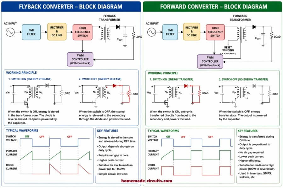
In these forward converter circuits, the transformer transfers energy to the secondary side during the primary switching pulses. The output rectifier converts these pulses into DC while the output inductor and capacitor help to produce a smooth DC output. Since we are using Half-Bridge or Full H-Bridge switching, a separate transformer reset winding is generally not required, because the bridge applies alternating voltage to the transformer primary.
Half-Bridge / Full H-Bridge SMPS Transformer and LC Calculator
Calculate transformer turns, wire sizes, output inductor and output capacitor for a half-bridge or full H-bridge SMPS.
1. Transformer calculations
2. Output LC filter calculations
Important: This is a preliminary design calculator. It does not calculate core loss, exact copper loss, temperature rise, insulation distances, leakage inductance or switching transients. Verify the actual circuit and component datasheets before building the SMPS. Mains-powered circuits can cause fatal electric shock.
Now, this calculator has two main parts. First part that calculates the transformer, but second part that calculates the output LC filter.
Let us choose the SMPS topology first. We select Half-Bridge if our circuit uses two main switching transistors and the transformer primary gets about half of the DC bus voltage, then you select it. Select Full H-Bridge if your circuit uses four switching transistors and the primary gets approximately the full DC bus voltage, then you select that.
Then enter the minimum and maximum DC bus voltage, so these are the rectified DC voltages available to the switching circuit, but not the AC input voltage. Since a 220V AC supply can produce around 310V DC after rectification, the actual voltage will change with the mains supply and the circuit load. You must measure or calculate the real bus voltage for that design.
Next enter the required output voltage and output current. For a 56V battery charger delivering 5A, you enter 56V and 5A. The output power will be calculated as voltage multiplied by current.
We enter the switching frequency used by the bridge controller. If the controller operates at 40kHz, then enter 40. The calculator converts this into hertz for its calculations.
Maximum pulse width per polarity
After this, enter the maximum pulse width per polarity, so this means the percentage of the complete switching cycle for which the primary receives one polarity of voltage. That is not the total duty of both polarities together. You do not enter 90% just because the output rectifier produces two pulses during one full switching cycle. The example uses 45%, but you must use a value that matches the real controller and its dead time.
Ferrite core effective area
Next you enter the ferrite core effective area Ae, and that value comes from the core datasheet, so it is usually given in square millimetres. You do not guess this value from the outside dimensions of the core.
Flux swing
Now enter the allowed flux swing, so this is the change in magnetic flux density during one active primary pulse, from one extreme to the other. The suitable value depends on the ferrite material, frequency, temperature and design. Since a lower value generally needs more primary turns, but it gives more margin against saturation.
The calculator uses the maximum DC bus voltage and the maximum pulse width to calculate the primary turns, so that is the conservative case for the entered values because the highest primary voltage can produce the highest flux swing. It then calculates the secondary turns needed to provide the required output at the minimum DC bus voltage.
The turns ratio tells you how many primary turns there are compared with the secondary turns. For example, a ratio of 5 to 1 means five primary turns for each secondary turn. The actual number of turns is rounded up to a whole number.
The primary and secondary pulse voltage results are estimates of the voltage applied to the windings during their active switching pulses. That is not the final DC output voltage, but the rectifier, output inductor, capacitor and losses all affect the final output.
Wire size
The wire size section estimates the current in the transformer windings and calculates the required copper area using the current density entered by you. The diameter shown is an equivalent solid wire diameter. At high switching frequencies, one thick wire may not be the best choice, so several thinner wires or suitable litz wire may be needed.
The window area is optional. If you know the usable bobbin window area from the core datasheet, then you enter it. The calculator gives a rough copper fill check but that is not an exact winding-fit calculation because it does not include all insulation, bobbin walls, wire enamel, winding layers or spacing requirements.
Now comes the output LC filter section.
The rectified secondary pulse frequency is assumed to be twice the switching frequency since the tool assumes a full-wave rectifier. For example, a 40kHz switching frequency gives an estimated 80kHz rectified pulse frequency, so this assumption must match your actual transformer and rectifier arrangement.
The inductor ripple percentage tells the calculator how much ripple current is allowed in the output inductor. If the output current is 5A and ripple is set to 20%, then the target ripple current is 1A peak-to-peak.
The calculator then estimates the output inductor value from the secondary pulse voltage, output voltage, effective duty cycle, rectified pulse frequency and allowed ripple current. The inductor must also have a suitable current rating and a core that will not saturate at the peak current.
The output capacitor calculation estimates how much capacitance is needed to keep the capacitive ripple within the target. It also estimates the extra ripple caused by the capacitor ESR. The total ripple shown is an approximate sum of those two parts.
You enter the available capacitance and ESR if you already have a capacitor bank in mind, then the calculator compares the estimated ripple with your target. It also estimates the capacitor ripple current, but you must check the actual capacitor datasheet and use a suitable temperature and lifetime rating.
The critical inductance result is a simplified estimate related to the boundary between continuous and discontinuous inductor current. That is not a substitute for checking the real inductor waveform at minimum load and maximum load.
A few important things must be remembered.
This tool does not calculate the core loss, exact winding temperature, transformer leakage inductance, insulation distances, MOSFET switching spikes or the actual controller waveforms. It also assumes balanced positive and negative transformer drive. If the two polarities are not balanced, then the transformer can develop flux walking and saturate even when the calculated turns look correct, so we must be careful.
The output LC section assumes a conventional full-wave rectifier and a buck-like output filter. If your circuit uses a different secondary winding arrangement or rectifier connection then the calculated results may not match the real circuit.