If you are wondering if there's an easy way to implement an H-bridge driver circuit without using the complex bootstrapping stage, the following idea will precisely solve your query.
In this article I have explained how to build an universal full-bridge or H-bridge MOSFET driver circuit, using P-channel and N-channel MOSFETs, which can be used for making high efficiency driver circuits for motors, inverters, and many different power converters.
The idea exclusively gets rid of the standard 4 N-channel H-bridge driver topology, which imperatively depends on the complex bootstrapping network.
Advantages and Disadvantages of Standard N-Channel Full Bridge Design
We know that full bridge MOSFET drivers are best achieved by incorporating N-channel MOSFETs for all the 4 devices in the system. The main advantage being the high degree of efficiency provided by these systems in terms of power transfer, and heat dissipation.
This is due to the fact that N-channel MOSFETs are specified with minimal RDSon resistance across their drain source terminals, ensuring minimum resistance to current, enabling smaller heat dissipation and smaller heatsinks on the devices.
However, implementing the above is not easy, since all the 4 channel devices cannot conduct and operate the central load without having a diode/capacitor bootstrapping network attached with the design.
Bootstrapping network requires some calculations, and tricky placement of the components to ensure that the systems works correctly. This appears to be the main disadvantage of a 4 channel MOSFET based H-bridge topology, that common users find difficult to configure and implement.
An Alternative Approach
An alternative approach to making an easy and universal H-bridge driver module that promises high efficiency and yet gets rid of the complex bootstrapping is by eliminating the two high side N-channel MOSFETs, and replacing them P-channel counterparts.
One may wonder, if it's so easy and effective then why is it not a standard recommended design? The answer is, although the approach looks simpler there are a few downsides which may cause lower efficiency in this type of full bridge configuration using P and N channel MOSFET combo.
Firstly, the P-channel MOSFETs usually higher RDSon resistance rating compared to N-channel MOSFETs, which may result in uneven heat dissipation on the devices and unpredictable output results. Second danger may be a shoot-through phenomenon, which can cause an instant damage to the devices.
That said, it is much easier to take care of the above two hurdles than designing a dicey bootstrapping circuit.
The two above issues can be eliminated by:
- Selecting P-channels MOSFETs with lowest RDSon specifications, which may be almost equal to the RDSon rating of the complementary N-channel devices. For example in our proposed design, you can find IRF4905 being used for the P-channel MOSFETs, which are rated with an impressively low RDSon resistance of 0.02 Ohms.
- Countering the shoot-through by adding appropriate buffer stages, and by using oscillator signal from a reliable digital source.
An Easy Universal H-Bridge MOSFET Driver
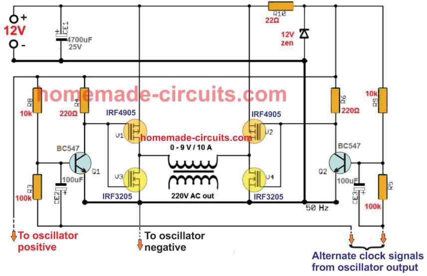
The following image shows the P-channel/N-channel based universal H-bridge MOSFET driver circuit, which seems to be designed to provide maximum efficiency with minimum risks.
How it Works
The working of the above H-bridge design is pretty much basic. The idea is best suited for inverter applications for efficiently converting a low power DC to mains level AC.
The 12V supply is acquired from any desired power source, such as from a battery or solar panel for an inverter application.
The supply is conditioned appropriately using the 4700 uF filter capacitor and through the 22 ohm current limiting resistor and a 12V zener for added stabilization.
The stabilized DC is used for powering the oscillator circuit, ensuring that its working is not affected by the switching transients from the inverter.
The alternate clock output from the oscillator are fed to the bases of the Q1, Q2 BJTs which are standard small signal BC547 transistor positioned as buffer/inverter stages for driving the main MOSFET stage with precision.
By default, the BC547 transistors are in the switched ON condition, through their respective base resistive divider potentials.
This means that the in the idle condition, without the oscillator signals, the P-channel MOSFETs are always switched ON, while the N-channel MOSFETs are always switched OFF. In this situation, the load at the center, which is a transformer primary winding gets no power and remains switched OFF.
When clock signals are fed to the indicated points, the negative signals from the clock pulses actually ground the base voltage of the BC547 transistors via the 100 uF capacitor.
This happens alternately, causing the N-channel MOSFET from one of the arms of the H-bridge to turn ON. Now, since the P-channel MOSFET on the other arm of the bridge is already switched ON, enables one P-channel MOSFET and one N-channel MOSFET across the diagonal sides to get switched ON simultaneously, causing the supply voltage to flow across these MOSFETs and the primary of the transformer in one direction.
For the second alternate clock signal, the same action repeats, but for the other diagonal arm of the bridge causing the supply to flow through the transformer primary in the other direction.
The switching pattern is exactly similar to any standard H-bridge, as depicted in the following figure:
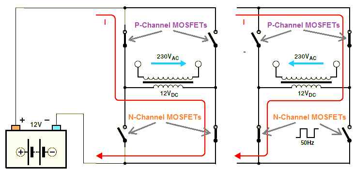
This flip-flop switching of the P and N channel MOSFETs across the left/right diagonal arms keep repeating in response to the alternate clock signal inputs from the oscillator stage.
As a result, the transformer primary is also switched in the same pattern causing a square wave AC 12V to flow across its primary, which is in correspondingly converted into 220 V or 120 V AC square wave across the secondary of the transformer.
The frequency is dependent on the frequency of the oscillator signal input which can be 50 Hz for 220 V output and 60 Hz for 120 V AC output,
Which Oscillator Circuit can be Used
The oscillator signal can be from any digital IC based design, such as from the IC 4047, SG3525, TL494, IC 4017/555, IC 4013 etc.
Even transistorized astable circuit can be used effectively for the oscillator circuit.
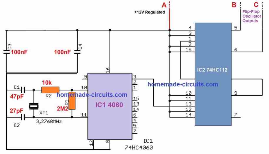
The following oscillator circuit example can be ideally used with the above discussed full bridge module. The oscillator has a fixed at 50 Hz output, through a crystal transducer.


Comments
I have project to feed 240 VAC Enphase micro inverters with grid simulated 240 VAC sine wave signal. The main problem I have is reverse current. I have to have Reverse Blocking IGBT . I feed from 240 VAC pure sine wave inverter to transformer 240 to 240 VAC to bridge rectifier for 240 vac to 240vdc to H bridge IGBT . What driver I need for IGBT to have sine wave 240 vac output. It is very crude circuits to simulate the grid 240 vac. only concern is reverse current to not blow the circuit
Hi Swagatam,thanks for helping us to make our homemade projects.Is it possible to use more powerfull mosfets with (V drain-source = 200v or 500v) with the same V gate-source in this circuit?
Thank you tirdad, yes that’s possible, you can replace the mosfets with higher specification mosfet, however you will have to make sure that the RDsON spec of the P and N channel mosfets are almost similar.
The gate voltage can be the same for the higher voltage rated mosfets also, between 10 and 20 V
Hi sir,
i have a problem on how to use the datasheets in choosing the write components to use in my FULL BRIDGE CLASS D 500W SUPPLYING A LOAD OF 8 OHMS.can you please help me.
Hi Peter, are you referring to the MOSFET specifications for your 500 watt inverter??
Am I understanding this correctly, this 12V is being to 220V ? Can you clarify this a little bit more?
yes it is a DC to AC inverter circuit!
I found the solution in your posts.
Thanks again . ♥️
No problem!
this idea looks superb,i will try it out and give feedback. Thanks for your endless hardwork.
Glad you liked it, hope it works for you!
And how can i transform a dc voltage to frequency?
Dear Mr Swagatam
Is there any simple circuits which can measure duty cycle.
Thanks in advance for your kindness
Dear Ehsan, a DC voltmeter can be used for judging the duty cycle, since the average voltage value for the duty cycles will be directly proportional to the DC volts on the meter.
very interesting, i have a lot of questions for you, I need you send me an a mail for me to send you some circuits I.ve got to do and easy simple welder inverter to 160A