• Skip to primary navigation
  • Skip to main content
  • Skip to primary sidebar

Homemade Circuit Projects

Get free circuit help 24/7

  • 1000+ Circuits
  • Privacy Policy
  • About Us
  • Contact
  • Disclaimer
  • Videos – Circuit Test Results
You are here: Home / Solar Controllers / How to Make a Solar Cell from a Transistor

How to Make a Solar Cell from a Transistor

Last Updated on April 6, 2020 by Swagatam 4 Comments

The majority of newbie electronic hobbyists would certainly have a couple of burned up power transistors such as 2N3055 hiding inside their junk box.

Supposing we have their internal semiconductor junctions still intact, the device could be transformed into a nice little solar cell by filing or sawing off the top cap of the device, in order to uncover the internal embedded chip die.

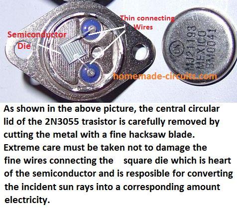
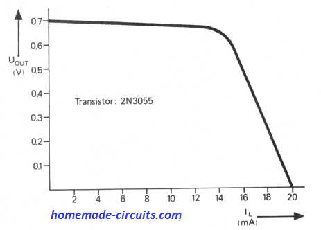
How much Current can be Generated with a 2N3055 Solar Cell?

When this 2N3055 chip semiconductor is exposed strong sunlight, will probably crank out approximately 0.7 V at currents as high as 20 mA. The graph demonstrates output voltage drawn versus load current.

How to Increase Curent

Since the surface area of the silicon chip is tiny when compared to a standard solar cell you may need a magnifying glass or a convex lens to concentrate sun rays over the silicon die chip in order to boost the output current.

On the other hand, extremely strong concentrated sunlight is strictly not advised, which may otherwise permanently burn the transistor junction!

Advantage of Using New 2N3055

In case a transistor in good condition is utilized then you may find the output current doubled, when the collector-base and emitter-base junction a are wired up parallel, as indicated in the circuit diagram.

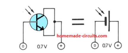
This may not be possible if the transistor is already faulty. This is because a damaged transistor may have a faulty junction which may be short-circuited, causing a short at the output of the solar cell.

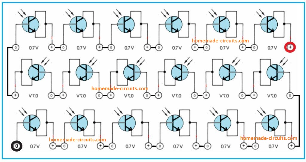
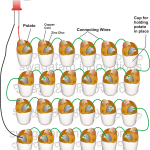
How to get 12 V from 2N3055 Solar Cell

To get 12 V from 2N3055 customized solar cells, you may have to join 18 of these in series, as demonstrated in the following diagram.

Since each device is capable of producing around 0.7 V, the total voltage generated could be around 0.7 x 18 = 12.6 V. However, the maximum current wouldn't change and be still around 40 mA.

Warning: Please do not use the outdated Germanium power transistors, because these types may possibly include extremely toxic ingredients. On the other hand, a leading semiconductor producer have ascertained that the more contemporary silicon devices, including the 2N3055, are absolutely safe in this regard.


Previous: High Power DC to DC Converter Circuit – 12 V to 30 V Variable
Next: Function Generator Circuit using a Single IC 4049

About Swagatam

I am an electronic engineer (dipIETE ), hobbyist, inventor, schematic/PCB designer, manufacturer. I am also the founder of the website: https://www.homemade-circuits.com/, where I love sharing my innovative circuit ideas and tutorials.
If you have any circuit related query, you may interact through comments, I'll be most happy to help!

You'll also like:

  • 1.  Remote Controlled Solar Lamp Intensity Controller Circuit
  • 2.  Generate Electricity from your Gym Workout
  • 3.  Solar Inverter for 1.5 Ton Air Conditioner
  • 4.  How to Generate Electricity from Road Speed Breakers
  • 5.  How to Make Simple Solar Cooker at Home
  • 6.  48V Solar Battery Charger Circuit with High/Low Cut-off

Please Subscribe (Only if you are Genuinely Interested in our Newsletters)


Reader Interactions

Comments

    Your Comments are too Valuable! But please see that they are related to the above article, and are not off-topic! Cancel reply

    Your email address will not be published. Required fields are marked *

  1. Search Related Posts for Commenting

  2. Swagatam says

    Hi please provide the technical specifications of the LED backlight, I’ll try to figure it out for you

    Reply
  3. Donatus says

    Thanks for your information sir.
    How can it be connected in parallel to increas current. I want to try it.

    Reply
    • Swagatam says

      Make many of these 12V modules, and simply connect their +/- together.

      Reply
  4. wayne chamberlain says

    hi,
    1 i would like a drum circuit that uses a twin t oscillator. thanks.
    2 if you want a solar cell power supply use the cells out of solar walk lights.
    3 when you install them for the original use, grease the battery ends as the battery usually leaks and corrodes the terminals.

    Reply


  5. COMMENT BOX IS MOVED AT THE TOP


Primary Sidebar

Electronic Projects Categories

  • 3-Phase Power (15)
  • 324 IC Circuits (19)
  • 4017 IC Circuits (51)
  • 4060 IC Circuits (25)
  • 555 IC Circuits (92)
  • 741 IC Circuits (18)
  • Amplifiers (49)
  • Arduino Engineering Projects (82)
  • Audio Projects (83)
  • Battery Chargers (75)
  • Car and Motorcycle (87)
  • Datasheets (44)
  • Decorative Lighting (Diwali, Christmas) (31)
  • DIY LED Projects (81)
  • Electronic Components (96)
  • Electronic Devices and Circuit Theory (34)
  • Electronics Tutorial (99)
  • Fish Aquarium (5)
  • Free Energy (34)
  • Games (2)
  • GSM Projects (9)
  • Health Related (17)
  • Heater Controllers (23)
  • Home Electrical Circuits (98)
  • Incubator Related (6)
  • Industrial Electronics (25)
  • Infrared (IR) (39)
  • Inverter Circuits (94)
  • Laser Projects (10)
  • LM317/LM338 (21)
  • LM3915 IC (24)
  • Meters and Testers (52)
  • Mini Projects (152)
  • Motor Controller (64)
  • MPPT (7)
  • Oscillator Circuits (12)
  • PIR (Passive Infrared) (8)
  • Power Electronics (32)
  • Power Supply Circuits (65)
  • Radio Circuits (9)
  • Remote Control (46)
  • Security and Alarm (55)
  • Sensors and Detectors (115)
  • SG3525 IC (4)
  • Simple Circuits (72)
  • SMPS (30)
  • Solar Controllers (60)
  • Timer and Delay Relay (51)
  • TL494 IC (5)
  • Transformerless Power Supply (8)
  • Transmitter Circuits (37)
  • Ultrasonic Projects (12)
  • Water Level Controller (45)

Follow Homemade Circuits

Facebook
Twitter
YouTube
Instagram
My Facebook-Page
Quora

Feeds

Post RSS
Comment RSS

Circuit Calculators

  • AWG to Millimeter Converter
  • Battery Back up Time Calculator
  • Capacitance Reactance Calculator
  • IC 555 Astable Calculator
  • IC 555 Monostable Calculator
  • Inductance Calculator
  • LC Resonance Calculator
  • LM317, LM338, LM396 Calculator
  • Ohm’s Law Calculator
  • Phase Angle Phase Shift Calculator
  • Power Factor (PF) Calculator
  • Reactance Calculator
  • Small Signal Transistor(BJT) and Diode Quick Datasheet
  • Transistor Astable Calculator
  • Transistor base Resistor Calculator
  • Voltage Divider Calculator
  • Wire Current Calculator
  • Zener Diode Calculator

© 2021 · Swagatam Innovations

We use cookies to ensure that we give you the best experience on our website. If you continue to use this site we will assume that you are happy with it.Ok