In this post I will show how to construct a digital capacitance meter circuit using Arduino which can measure capacitance of capacitors ranging from 1 microfarad to 4000 microfarad with reasonable accuracy.
Introduction
We measure value of the capacitors when the values written on the capacitor’s body is not legible, or to find the value of the ageing capacitor in our circuit which need to be replaced soon or later and there are several other reasons to measure the capacitance.
To find the capacitance we can easily measure using a digital multimeter, but not all multimeters have capacitance measuring feature and only the expensive multimeters have this functionality.
So here is a circuit which can be constructed and used with ease.
We are focusing on capacitors with larger value from 1 microfarad to 4000 microfarad which are prone to lose its capacitance due to ageing especially electrolytic capacitors, which consist of liquid electrolyte.
Before we go into circuit details, let’s see how we can measure capacitance with Arduino.
Most Arduino capacitance meter relies on RC time constant property. So what is RC time constant?
The time constant of RC circuit can be defined as time taken for the capacitor to reach 63.2 % of the full charge. Zero volt is 0 % charge and 100% is capacitor’s full voltage charge.
The product of value of resistor in ohm and value of capacitor in farad gives Time constant.
T = R x C
T is the Time constant
By rearranging the above equation we get:
C = T/R
C is the unknown capacitance value.
T is the time constant of RC circuit which is 63.2 % of full charge capacitor.
R is a known resistance.
The Arduino can sense the voltage via analog pin and the known resistor value can be entered in the program manually.
By applying the equation C = T/R in the program we can find the unknown capacitance value.
By now you would have an idea how we can find the value of unknown capacitance.
In this post I have proposed two kinds of capacitance meter, one with LCD display and another using serial monitor.
If you are frequent user of this capacitance meter it is better go with LCD display design and if you are not frequent user better go with serial monitor design because it save you some bucks on LCD display.
Now let’s move on to circuit diagram.
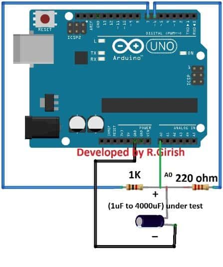
Serial Monitor based capacitance meter:

As you can see the circuit is very simple just a couple of resistors are needed to find the unknown capacitance.The 1K ohm is the known resistor value and the 220 ohm resistor utilized for discharging the capacitor while measurement process takes place.
The Arduino sense the rising and decreasing voltage on pin A0 which is connected between 1K ohm and 220 ohm resistors.Please take care of the polarity if you are using polarized capacitors such as electrolytic.
Program Code
//-----------------Program developed by R.Girish------------------//

const int analogPin = A0;
const int chargePin = 7;
const int dischargePin = 6;

const float resistorValue = 1000; // Value of known resistor in ohm

unsigned long startTime;
unsigned long elapsedTime;
float microFarads;

void setup()
{
  Serial.begin(9600);

  pinMode(chargePin, OUTPUT);
  digitalWrite(chargePin, LOW);

  pinMode(dischargePin, INPUT); // keep discharge off initially
}

void loop()
{
  // Start charging capacitor
  digitalWrite(chargePin, HIGH);
  startTime = millis();

  while (analogRead(analogPin) < 648)
  {
    // wait till capacitor reaches 63.2%
  }

  elapsedTime = millis() - startTime;

  microFarads = ((float)elapsedTime / resistorValue) * 1000;

  if (microFarads > 1)
  {
    Serial.print("Value = ");
    Serial.print((long)microFarads);
    Serial.println(" microFarads");

    Serial.print("Elapsed Time = ");
    Serial.print(elapsedTime);
    Serial.println(" mS");

    Serial.println("--------------------------------");
  }
  else
  {
    Serial.println("Please connect Capacitor!");
    delay(1000);
  }

  // Stop charging
  digitalWrite(chargePin, LOW);

  // Discharge capacitor
  pinMode(dischargePin, OUTPUT);
  digitalWrite(dischargePin, LOW);

  while (analogRead(analogPin) > 0)
  {
    // wait till capacitor fully discharges
  }

  pinMode(dischargePin, INPUT);
}

//-----------------Program developed by R.Girish------------------//
Upload the above code to Arduino with completed hardware setup, initially don’t connect the capacitor. Open the serial monitor; it says “Please connect capacitor”.
Now connect a capacitor, its capacitance will be displayed as illustrated below.
It also shows the time taken to reach 63.2% of the capacitor’s full charge voltage, which is shown as elapsed time.
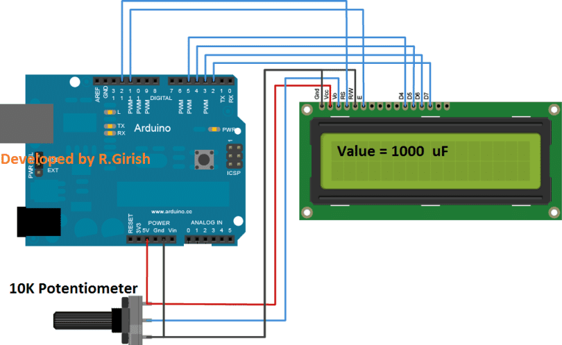
Circuit diagram for LCD based capacitance meter:
The above schematic is connection between LCD display and Arduino. The 10K potentiometer is provided for adjusting the contrast of the display. Rest of the connections are self-explanatory.
The above circuit is exactly same as serial monitor based design; you just need to connect LCD display.
Program for LCD based capacitance meter:
//----------------- Program developed by R.Girish ------------------//
#include <LiquidCrystal.h>

LiquidCrystal lcd(12, 11, 5, 4, 3, 2);

const int analogPin = A0;
const int chargePin = 7;
const int dischargePin = 6;

float resistorValue = 1000;   // Known resistor value in ohms

unsigned long startTime;
unsigned long elapsedTime;
float microFarads;

void setup()
{
  Serial.begin(9600);
  lcd.begin(16, 2);

  pinMode(chargePin, OUTPUT);
  digitalWrite(chargePin, LOW);

  pinMode(dischargePin, INPUT);

  lcd.clear();
  lcd.setCursor(0, 0);
  lcd.print(" CAPACITANCE");
  lcd.setCursor(0, 1);
  lcd.print(" METER");

  delay(1000);
}

void loop()
{
  // Start charging capacitor
  digitalWrite(chargePin, HIGH);
  startTime = millis();

  // Wait until capacitor reaches ~63% (ADC ≈ 648)
  while (analogRead(analogPin) < 648)
  {
    // safety: allow exit if something goes wrong
  }

  elapsedTime = millis() - startTime;

  // Calculate capacitance in microfarads
  microFarads = ((float)elapsedTime / resistorValue) * 1000.0;

  lcd.clear();

  if (microFarads > 1)
  {
    lcd.setCursor(0, 0);
    lcd.print("Value = ");
    lcd.print((long)microFarads);
    lcd.print(" uF");

    lcd.setCursor(0, 1);
    lcd.print("Elapsed:");
    lcd.print(elapsedTime);
    lcd.print(" mS");
  }
  else
  {
    lcd.setCursor(0, 0);
    lcd.print("Please connect");
    lcd.setCursor(0, 1);
    lcd.print("capacitor !!!");
  }

  delay(500);

  // Stop charging
  digitalWrite(chargePin, LOW);

  // Discharge capacitor fully
  pinMode(dischargePin, OUTPUT);
  digitalWrite(dischargePin, LOW);

  while (analogRead(analogPin) > 0)
  {
    // wait for complete discharge
  }

  pinMode(dischargePin, INPUT);
}
//----------------- Program developed by R.Girish ------------------//
With the completed hardware setup upload the above code. Initially don’t connect the capacitor. The display shows “Please connect capacitor!!!” now you connect the capacitor. The display will show the capacitor’s value and elapsed time taken to reach 63.2% of full charge capacitor.
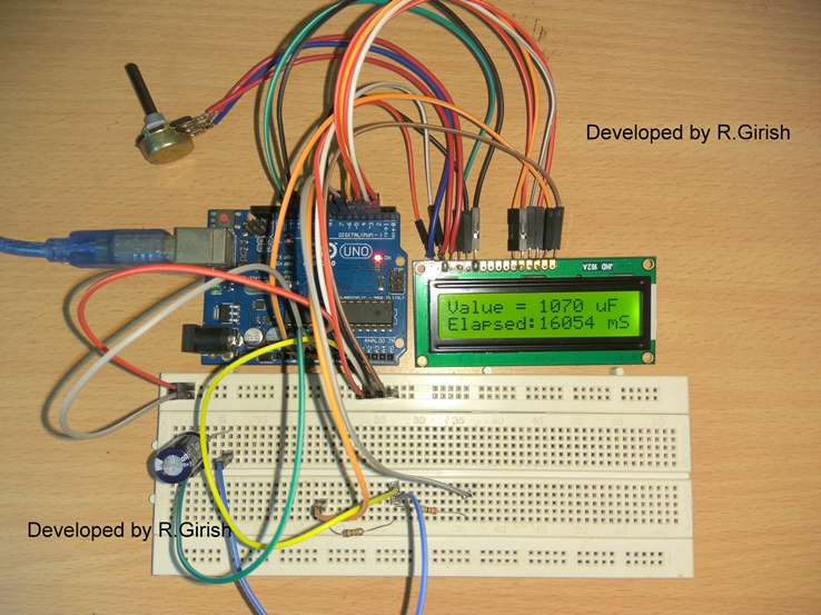
Author’s Prototype:


Comments
to u and yr family.
Sr i want to glow up 7000 to 8000 leds with 220 v ac and want them just blinking.
Kindly guide and help me giving a appropriate ckt.
Thanks and best regards in advance
Madina, you can use the designs shown in the following link and connect LEDs in series and parallel at the points where the word load is specified..each series string should have 93 LEDs in series with a 1K/2 watt resistor
https://www.homemade-circuits.com/2013/07/simple-triac-timer-circuit.html
Hello sir can u send .net a circuit .of wifi in which range is 3 km
if it's possible we'll try to update it