I have designed and published a variety of battery charger circuits in this website, however the readers often get confused while selecting the right battery charger circuit for their individual applications.
And I have to explicitly explain each of the readers regarding how to customize the given battery charger circuit for their specific needs.
This becomes quite time consuming, since it's the same thing that I have to explain to each of the readers from time to time.
This compelled me to publish this post where I have tried to explain a standard battery charger design and how to customize it in several ways to suit individual preferences in terms of voltage, current, auto-cut-off or semi-automatic operations.
Charging Battery Correctly is Crucial
The three fundamental parameters that all batteries require in order to get charged optimally and safely are:
- Constant Voltage.
- Constant Current.
- Auto-cutoff .
So basically, these are the three fundamental things one needs to apply to successfully charge a battery and also make sure that the life of the battery is not affected in the process.
A few enhanced and optional conditions are:
Thermal management.
and Step charging.
The above two criteria are especially recommended for Li-ion batteries, while these may not be so crucial for lead acid batteries (although there's' no harm in implementing it for the same)
Let's figure out the above conditions step wise and see how one may be able to customize the requirements as per the following instructions:
Importance of Constant Voltage:
All batteries are recommended to be charged at a voltage that may be approximately 17 to 18% higher than the printed battery voltage, and this level must not be increased or fluctuated by much.
Therefore for a 12V battery, the value comes to around 14.2V which should not be increased by much.
This requirement is referred to as the constant voltage requirement.
With the availability of a number voltage regulator ICs today, making a constant voltage charger is a matter of minutes.
The most popular among these ICs are the LM317 (1.5 amps), LM338 (5amps), LM396 (10 amps). All these are variable voltage regulator ICs, and allow the user to set any desired constant voltage anywhere from 1.25 to 32V (not for LM396).
You can use the IC LM338 which is suitable for most of the batteries for achieving a constant voltage.
Here's an example circuit which can be used for charging any battery between 1.25 and 32V with a constant voltage.
Constant Voltage Battery Charger Schematic
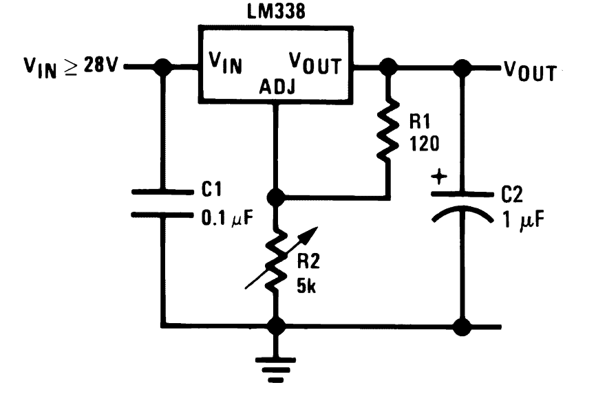
Varying the 5k pot enables setting of any desired constant voltage across the C2 capacitor (Vout) which can be used for charging a connected battery across these points.
For fixed voltage you could replace R2 with a fixed resistor, using this formula:
VO = VREF (1 + R2 / R1) + (IADJ × R2)
Where VREF is = 1.25
Since IADJ is too small it can be ignored
Although a constant voltage may be necessary, in places where the voltage from an input AC mains does not vary too much (a 5% up/down is quite acceptable) one may entirely eliminate the above circuit and forget about the constant voltage factor.
This implies that we can simply use a correctly rated transformer for charging a battery without considering a constant voltage condition, provided the mains input is fairly dependable in terms of its fluctuations.
Today with the advent of SMPS devices, the above issue completely becomes immaterial since SMPS are all constant voltage power supplies and are highly reliable with their specs, so if an SMPS is available, the above LM338 circuit can be definitely eliminated.
But commonly an SMPS comes with a fixed voltage, so in that case customizing it for a particular battery might become an issue and you may have to opt for the versatile LM338 circuit as explained above.... or if you still want to avoid this, you may simply modify the SMPS circuit itself for acquiring the desired charging voltage.
The following section have explained the designing of a customized current control circuit for a specific, selected battery charger unit.
Adding a Constant Current
Just like the "constant voltage" parameter, the recommended charging current for a particular battery should not be increased or fluctuated by much.
For lead acid batteries, the charging rate should be approximately 1/10th or 2/10th of the printed Ah (Ampere Hour) value of the battery. meaning if the battery is rated at say 100Ah, then its charging current (amp) rate is recommended to be at 100/10 = 10 Ampere minimum or (100 x 2)/10 = 200/10 = 20 amp maximum, this figure should not be increased preferably to maintain healthy conditions for the battery.
However for Li-ion or Lipo batteries the criterion is entirely different, for these batteries the charging rate could be as high as their Ah rate, meaning if the AH spec of a Li-ion battery is 2.2 Ah then it's possible to charge it at the same level that is at 2.2 ampere rate Here you don't have to divide anything or indulge in any kind of calculations.
For implementing a constant current feature, again a LM338 becomes useful and can be configured for achieving the parameter with a high degree of accuracy.
The below given circuits show how the IC may be configured for implementing a current controlled battery charger.
Make sure to check out this article which provides an excellent, and highly customizable battery charger circuit.
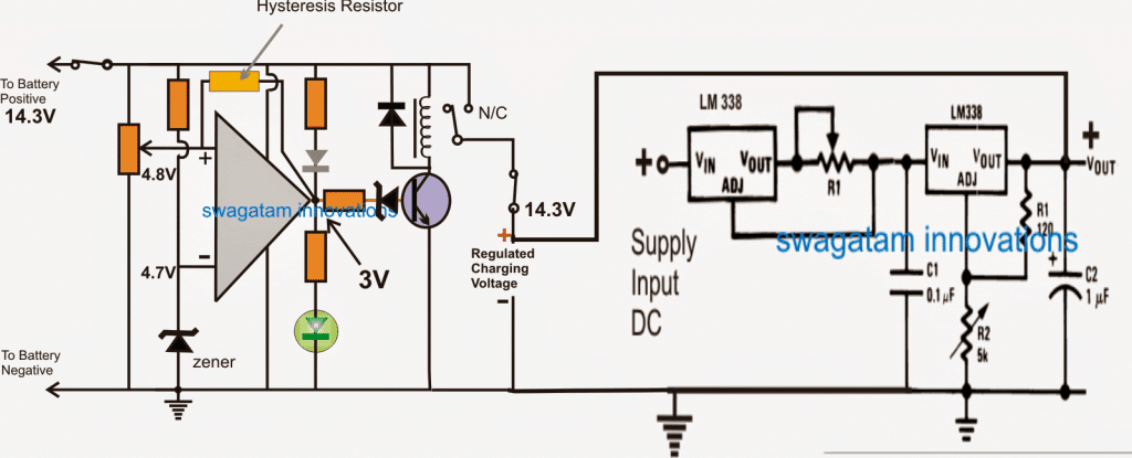
Schematic for CC and CV Controlled Battery Charger
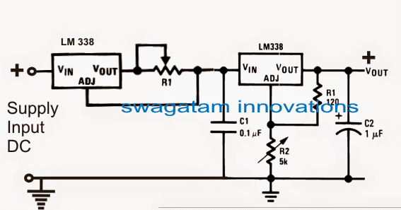
As discussed in the previous section, in case your input mains is fairly constant, then you can ignore the right hand side LM338 section, and simply use the left side current limiter circuit with either a transformer or an SMPS, as shown below:
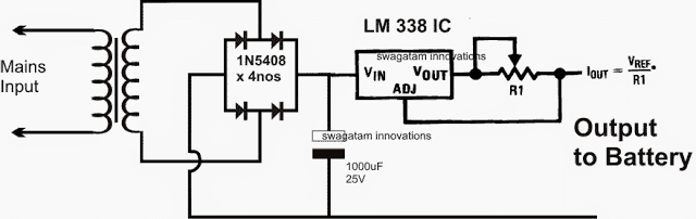
In the above design, the transformer voltage may be rated at the battery voltage level, but after rectification it might yield a little above the specified battery charging voltage.
This issue can be neglected because the attached current control feature will force the voltage to automatically sink the excess voltage to the safe battery charging voltage level.
R1 can be customized as per the needs, by following the instructions furnished HERE
The diodes must be appropriately rated depending on the charging current, and preferably should be much higher than the specified charging current level.
Customizing current for charging a battery
In the above circuits the referred IC LM338 is rated to handle at the most 5 amps, which makes it suitable only for batteries upto 50 AH, however you may have much higher rated batteries in the order of 100 AH, 200 AH or even 500 AH.
These might require charging at the respective higher current rates which a single LM338 might not be able to suffice.
To remedy this one can upgrade or enhance the IC with more ICs in parallel as shown in the following example article:
In the above example, the configuration looks little complicated due to the inclusion of an opamp, however a little tinkering shows that actually the ICs can be directly added in parallel for multiplying the current output, provided that all the ICs are mounted over a common heatsink, see the below diagram:
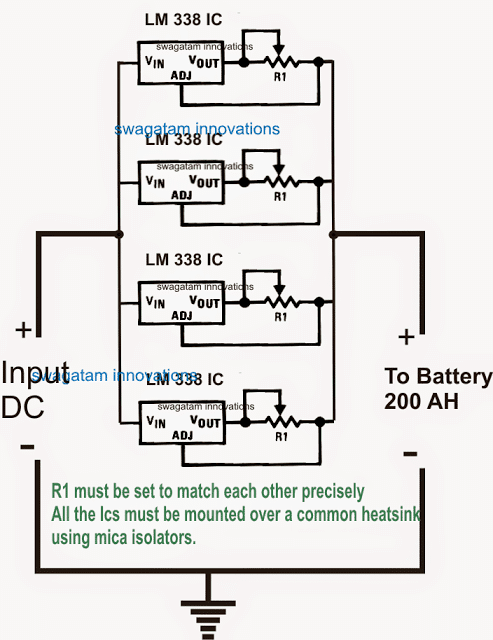
Any number of ICs may be added in the shown format for achieving any desired current limit, however two things must be ensured in order to get an optimal response from the design:
All the ICs must be mounted over a common heatsink, and all the current limiting resistors (R1) must be fixed with a precisely matching value, both the parameters are required to enable an uniform heat sharing among the ICs and hence equal current distribution across the output for the connected battery.
So far we have learned regarding how to customize constant voltage and constant current for a specific battery charger application.
However without an auto cut-off a battery charger circuit may be just incomplete and quite unsafe.
So far in our battery charging tutorials I have explained how to customize constant voltage parameter while building a battery charger, in the following sections I will try to explain how to implement a full charge auto cut off for assuring a safe charging for the connected battery.
Adding an Auto-Cut 0ff in Battery Charger
In this section we'll discover how an auto cut-off may be added to a battery charger which is one of the most crucial aspects in such circuits.
A simple auto cut-off stage can be included and customized in a selected battery charger circuit by incorporating an opamp comparator.
An opamp may be positioned to detect a rising battery voltage while it's being charged and cut off the charging voltage as soon as the voltage reaches the full charge level of the battery.
You might have already seen this implementation in most of the automatic battery charger circuits so far published in this blog.
The concept may be thoroughly understood with the help of the following explanation and the shown circuit GIF simulation:
NOTE: Please use the relay N/O contact for the charging input, instead of the shown N/C. This will ensure that the relay does not chatter in the absence of a battery. For this to work, also make sure to swap the input pins (2 and 3) with each other.
In the above simulation effect we can see that an opamp is been configured as a battery voltage sensor for detecting the over charge threshold, and cutting off the supply to the battery as soon as this is detected.
The preset at pin (+) of the IC is adjusted such that at full battery voltage (14.2V here), the pin#3 acquires a shade higher potential than the pin (-) of the IC which is fixed with a reference voltage of 4.7V with a zener diode.
The previously explained "constant voltage" and "constant current" supply is connected to the circuit, and the battery via the N/C contact of the relay.
Initially the supply voltage and the battery both are switched off from the circuit.
First, the discharged battery is allowed to be connected to the circuit, as soon as this is done, the opamp detects a potential that's lower (10.5V as assumed here) than the full charge level, and due to this the RED LED comes ON, indicating that the battery is below the full charge level.
Next, the 14.2V input charging supply is switched ON.
As soon as this is done, the input instantly sinks down to the battery voltage, and attains the 10.5V level.
The charging procedure now gets initiated and the battery begins getting charged.
As the battery terminal voltage increases in the course of the charging, the pin (+) voltage also correspondingly increases.
And the moment the battery voltage reaches the full input level that is the 14.3V level, the pin (+) also proportionately attains a 4.8V which is just higher than the pin (-) voltage.
This instantly forces the opamp output to go high.
The RED LED now switches OFF, and the green LED illuminates, indicating the changeover action and also that the battery is fully charged.
However what may happen after this is not shown in the above simulation. We'll learn it through the following explanation:
As soon as the relay trips the battery terminal voltage will quickly tend to drop and restore to some lower level since a 12V battery will never hold a 14V level consistently and will try to attain a 12.8V mark approximately.
Now, due to this condition, the pin (+) voltage will again experience a drop below the reference level set by pin (-), which will yet again prompt the relay to switch OFF, and the charging process will be again initiated.
This ON/OFF toggling of the relay will keep on cycling making an undesirable "clicking" sound from the relay.
To avoid this it becomes imperative to add a hysteresis to the circuit.
This is done by introducing a high value resistor across the output and the (+) pin of the IC as shown below:
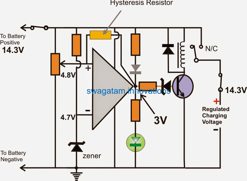
Adding Hysteresis
The addition of the above indicated hysteresis resistor prevents the relay oscillating ON/OFF at the threshold levels and latches the relay up to a certain period of time (until the battery voltage drops below the sustainable limit of this resistor value).
Higher value resistors provide lower latching periods while lower resistor provide higher hysteresis or higher latching period.
Thus from the above discussion we can understand how a correctly configured automatic battery cut-off circuit may be designed and customized by any hobbyist for his preferred battery charging specs.
Now lets see how the entire battery charger design may look including the constant voltage/current set up along with the above cut-off configuration:
So here's the completed customized battery charger circuit which can be used for charging any desired battery after setting it up as explained in our entire tutorial:
- The opamp can be a IC 741
- The preset = 10k preset
- both zener diodes can be = 4.7V, 1/2 watt
- zener resistor = 10k
- LED and transistor resistors can be also = 10k
- Transistor = BC547
- relay diode = 1N4007
- relay = select match the battery voltage.
How to Charge a Battery without any of the Above Facilities
If you are wondering whether it is possible to charge a battery without associating any of the above mentioned complex circuits and parts?
The answer is yes, you can charge any battery safely and optimally even if you do not have any of the above mentioned circuits and parts.
Before proceeding it would be important to know the few crucial things a battery requires to charge safely and the things that make "auto cut off" "constant voltage" and "constant current" parameters so important.
These features become important when you want your battery to be charged with extreme efficiency and quickly. In such cases you may want your charger to be equipped with many advanced features as suggested above.
However if you are willing to accept the full charge level of your battery slightly lower than optimal, and if you willing to provide a few hours more for the charging to finish, then certainly you wouldn't require any of the recommended features such as constant current, constant voltage or auto cut off, you can forget all these.
Basically a battery should not be charged with supplies having higher rating than the battery's printed rating, it is as simple as that.
Meaning suppose your battery is rated at 12V/7Ah, ideally you must never exceed the full charge rate above 14.4V, and current over 7/10 = 0.7 amps.
If these two rates are correctly maintained, you can rest assured that your battery is in safe hands, and will never get harmed regardless of any circumstances.
Therefore in order to ensure the above mentioned criteria and to charge the battery without involving complex circuits, just make sure the input supply that you are using are rated accordingly.
For example if you charging a 12V/7Ah battery, select a transformer which produces around 14V after rectification and filtration, and its current is rated at around 0.7 ampere.
The same rule may be applied for other batteries also, proportionately.
The basic idea here is to keep the charging parameters slightly lower than the maximum permissible rating.
For example a 12V battery may be recommended to be charged upto 20% higher than its printed value, that is 12 x 20% = 2.4V higher than 12V = 12 + 2.4 = 14.4V.
Therefore we make sure to keep this slightly lower at 14V, which may not charge the battery to its optimal point, but will be just good for anything, in fact keeping the value slightly lower will enhance the battery life allowing many more charge/discharge cycles in the long run.
Similarly, keeping the charging current at 1/10th of the printed Ah value makes sure that the battery is charged with minimum stress and dissipation, rendering a longer life to the battery.
The Final Setup
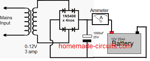
A simple set up shown above can be universally used for charging any battery safely and quite optimally, provided you allow sufficient charging time or until you find the needle of the ammeter dropping down to almost zero.
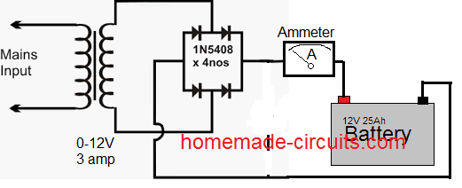
The 1000uf filter capacitor is actually not needed, as shown above, and eliminating it would actually enhance the battery life.
Have further doubts? Do not hesitate to express them through your comments.
Source: battery charging


Comments
Does anyone have a schematic for a battery charger that will charge a pack that supplies both + voltage and – voltage?
I used DC meter in series with the rectified line for battery charging
Connect the DC meter directly to ground (without battery) and measure the current for a second and remove it…check this this individually after rectification for the two transformers, and also in parallel after rectification…
Thanks sir, I have checked it, all testings to ground gave Zero amps readings
Dan, zero amps means your transformer is not generating any current? How can that be?
Please check the range of the meter and set it to match the transformer maximum current rating and check again…
OK sir, but when connected to the battery, there was voltage increase.
It is difficult to judge the fault without a practical testing. A transformer rectified output will always show current when a meter is connected across the DC +/- outputs…
Hello sir, I built 2 small trafo chargers, when tested separately produced 14v, 0.15amps for the first, the other produced 14v, 0.59amps, but in parallel they produced 1.10amps, 14v to charge battery. Please why this,sir?
Hello Dan, how did you check the current outputs from the individuals trafos and then in parallel….I will try to figure out the issue..
hi bro , I am designing ev bike in that i have a 72v battery and 12v auxiliary battery …..the 72v battery is charged by charger in need to charge a this 12v auxiliary battery from 72v with 1A-2A…. can you suggest me it help me a lot
THANK YOU
Hey Ganesh,
This one appears to be the best design suitable for your application:
https://www.ti.com/lit/ds/symlink/lm5164.pdf
bro, I need to charge 12v auxiliary battery with 72v battery with 1A-2A
Hi Ganesh,
You will need a regulated buck converter for this application:
https://www.homemade-circuits.com/calculating-inductor-value-in-smps/
we are a battery Start-up and have developed a new type of battery with a different chemistry. we want to develop a battery charger for this battery which would be used for charging the battery packs of different types of electric vehicles having different voltage requirement like 12×4=48v for erickshaw, 12×5/6=60/72v for 2-wheelers, 12×8/10/12=96/120/144v for cars/trucks/trailers etc.
we need the charging at 0.5c to 4c for battery capacities ranging from 50AH to 500AH.
could you please guide us to develop simple, low cost & reliable battery chargers with functions to adjust the voltage & current as required.
We also need auto cut-off plus a temperature sensor & controller by limiting/reducing the input current if the battery temperature starts increasing beyond a particular limit.
please contact at the below mentioned email ID mohindersinghwahi1967@gmail.com or directly on whattsapp number +917385081488
Hello Mohinder,
If your battery is able to accept charging current at 4C rate, then that’s an outstanding feature and that also means it can be quickly charged within 15 minutes.
I can definitely provide you with a simple yet highly efficient and effective BMS type charger circuit for your battery.
Just give me one day, I will get back to you soon with the circuit idea.
If possible please provide more technical details about your battery, so that I create a new article on this with your credentials which might help you to get more potential customers.
Sir, Namaskar I have a 3.7v, 3Amps chargeable 18650 type battery. Please tell me a transformer less circuit to charge it. I would be grateful to you.
Hello Ashu,
For a 3 Ah Li-ion battery the optimal charging current will need to be 1.5 amps, which is not feasible and not appropriate with a capacitive power supply, so you will need an SMPS circuit for this.
I would recommend using an existing mobile charger for this, by adding a 4.1V voltage regulator at the output.
Let me know if the idea works for you, or if you have any further doubts…
Sir, kya ye voltage regulator zener diode hi hai,ya kuchh aur kripya sujhaye aur yadi zener hai toh isse kaise connect karein
Ashu, you can use the following voltage regulator circuit example at the output of the mobile charger:
https://www.homemade-circuits.com/wp-content/uploads/2022/09/solar-regulator-emitter-follower.jpg
Please do the following modifications in the above circuit:
1) Replace solar panel with your mobile charger supply input
2) Replace the TIP35 with TIPP3055 (although TIP35 will also work)
3) Replace R1 with 330 ohms 1 watt
4) Replace the zener diode ZX with 5.6V 1 watt zener diode.
5) The 100uF can be a 100uF/25V capacitor or any nearby value will work.
Hi Swagatam;
I need a circuit which may control / limit not only DC voltage but also ampere between 1 – 30 Volts and maximum 15 Amperes. So please advise which circuit I may use.
Best Wishes.
Hi Suat, You can try the practical design from the following article:
https://www.homemade-circuits.com/how-to-design-a-stabilized-bench-power-supply-circuit/
Instead of using two transistors for the main pass transistor, you can replace it with the following single Darlington transistor.
https://www.homemade-circuits.com/50-amp-transistor-mj11032-mj11033-datasheet-pinout/
sir i need battery charger circuit to charge four lead acid batteries in series 130 -180 ah capacity.
regards
You can try the following circuit:
https://www.homemade-circuits.com/wp-content/uploads/2020/12/current-sensed-battery-chager-circuit.jpg
More information on this can found in the following article:
https://www.homemade-circuits.com/high-current-10-to-20-amp-automatic/
Good day Sir, I used my fridge on 150ah battery with 1.5kva inverter but not very cold as compared with someone’s 200ah(very cold).
Please how can I salvage this to use it with my 150ah battery.
Thanks Swag.
Hi Seun, it simply means that the 150 Ah is not able to provide sufficient current to the fridge which is bad for the fridge and the battery also. You must check the current using 150 Ah battery and with 200Ah battery, that will help to understand the problem. The current consumption should not be beyond 15% of the battery Ah rating
Thanks Swag, if supplementary solar panels are added, what will be the optimum current drawn?
The current consumption will depend on the load. The load decides how much current it needs to draw.
I meant if the load draws 10amps from battery only but if added solar system supplies 3amps, will only 7amps be drawn from the battery invariably.
Yes that’s’s correct!
Good day Sir, Swagatam, I have a few questions on battery charging.
1. I noticed a trafo charger was charging without rectifier, any effect?
2. It is a common practice to put capacitor to charger, but you recommended not to use, any effect? I even saw some using 10000uf.
,3. I noticed preset settings for auto cut off for 40ah battery and 100ah is different, why is it so. Is there a way to have a standardised settings for these sizes.
Hi Seun,
It is dangerous and impossible to charge a battery directly from transformer without a rectifier.
You can use a filter capacitor after the bridge for charging a battery, it is fine. But without a filter capacitor the battery is charged with 100 Hz ripple voltage which helps to prevent sulfation on the battery plates.
According to me the full charge voltage preset setting should be the same for all batteries. However the current (amp) setting of the charger must be changed according to the battery Ah spec.
Thanks Sir Swag, between 1000uf and 10000uf capacitor which is better and why?
Hi Seun,
10000uF will allow the battery to charge faster than 1000uF. However DC without filtration is better for charging lead acid batteries.
Making it faster, does it increase voltage or current?
Please do you have any circuit or component that boost charging current.
As the capacitor value increases the current and voltage both increase, but not beyond what the power supply can produce.
For boost charging you can refer to the following post:
Make this Fast Battery Charger Circuit
Thanks Sir, I appreciate.
Can desulfator help if capacitor is used.
Capacitor will prevent the desulfator from working normally and producing the intended results.
Hello Swagatam, in this post I saw another automatic cut off Goff explained. You have said for it to work, the input pins 2 and 3 should be swapped with each other. What do u mean with the “swap?”……joining together???
Hello Morris, swapping means interchanging the pinouts with each other.
Sir referring to the fig of CC,CV battery charger circuit using LM 317/ 338, you have used the CC stage first and then the CV stage using the second regulator chip.My doubt is ,can we connect the other way round also,viz CV stage first and then the CC stage? Does this affect the circuit performance in any way? Also pls let me know whether this circuit helps in accidental short circuit protection
Binoj, yes you can put CV first and CC next, no problem with that. You can connect them anyway round, no issues. The ICs are internally fully protected against overload and short circuit.
At the end of the article you say:
“The 1000uf filter capacitor is actually not needed, as shown above, and eliminating it would actually enhance the battery life”
How would removing it enhance the battery life?
That capacitor would smooth out the DC from the rectifier. Surely that’s better for the battery? Isn’t it?
Just trying to understand.
Thanks in advance.
A pulsating DC is probably better for a battery since it prevents the internal plates of the battery from sulfating, and thus helps to keep the battery healthy and long pasting.
If I have a 12 v 7 amp battery and I use a 12 Volt 1 amp transformer or precisely a 750 ma transformer then will it be safe to forget the peak output voltage which may be 20 volts without using any regulator ics ?
12V transformer will produce around 17 V,and not 20 V after full bridge rectification…and it would be fine to provide this peak level provided the charger is equipped with a 14.3 V auto cut off
Hi Yulianto, you can try the 4rth circuit diagram from the following article:
https://www.homemade-circuits.com/high-current-10-to-20-amp-automatic/
i use 5 battery serial. asumed 14volt x5 70v charger
hi sir, help me please,
i wont to build 70 volt 100ah lead acid battrey. where is schemstic match with my charger?
thank before.
It will work like a constant voltage. For applying a constant current you can add a transistor stage to the circuit as explained in the following article:
https://www.homemade-circuits.com/how-to-make-current-controlled-12-volt/
Thanks for reply. But if I use a 12 Volt 1 ampere transformer to charge a 12 Volt 7.2 A battery, then is it a constant voltage or a constant current charger ? Since most low cost chargers available in market use this technique along with an ammeter to charge batteries so I want to know ?