In this post I have explained a simple day, night triggered automatic door lock circuit, which can be used for autonomously unlocking a kennel door during day break, and locking it when night sets in.
The idea was requested by an avid reader of this blog, Mr. Norman, as given below.
Design Request and Specifications
I am working on a circuit to power a linear actuator.
I have connected a mechanism to translate the linear motion of the actuator into a rotational motion. When the actuator pushes, an 18mm linkage rotates 90 degrees which operates a latch bar to latch a dog door.
The idea is to allow the dogs to exit when daylight occurs and to latch the door during the night. It must have a one shot operation to prevent the linear actuator from burning up.
The circuit is supposed to power one relay in daylight and the other relay at dark which is supposed to latch and unlatch the dog door by powering the a vehicle door solenoid.
Circuit Description
The complete circuit diagram of the day/night triggered automatic door lock circuit is shown in the following figure.
The working of the circuit can be understood with the following points:
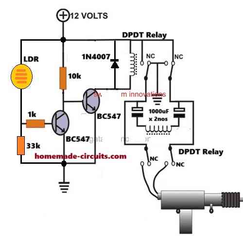
The day light and darkness detector is configured around the two BC547 transistor and the LDR circuit.
During day time the LDR resistance is low which allows the left side BC547 to remain switched ON. Due to this, the right side BC547 base is grounded and it is rendered switched OFF.
The above situation also keeps the upper DPDT relay turned OFF with its contacts resting at the N/C positions.
With the upper DPDT relay contacts at the N/C contacts keeps the lower relay also turned OFF and its contacts also remain at its N/C position.
Since the vehicle solenoid is configured with the N/O contacts of the lower relay, it also remains disabled in the current position.
In this switched OFF condition, the push-pull solenoid is initially set such that it stays in the retracted position, meaning its shaft is pulled inwards.
In this retracted position it allows the attached door lock (latch) to be in the open condition.
Hence, during day time the entire circuit remains disabled allowing the kennel door spindle to remain unlocked.
Now, during evening time when it starts getting darker, the LDR resistance increases. Finally, it reaches a point where no voltage can reach the base of the left side BC547 and it switches OFF.
As soon as the left side BC547 is switched OFF, the right side BC547 switches ON via the 10k biasing resistor, causing the upper DPDT relay to activate.
The contacts of the upper relay now shift to their N/O contacts causing a change of polarity for the voltage at its N/O contacts.
At this point, two things happen simultaneously.
The changed voltage polarity at the N/O contacts of the upper relay sends a momentary supply to the coil of the lower DPDT relay.
Due to this momentary supply, the lower relay activates so that its contacts now shift towards the N/O contacts.
Since the solenoid latch is configured with these N/O contacts of the lower relay, the solenoid now gets the required supply and it triggers ON causing its shaft to shoot and push outwards.
The above operation causes the attached door lock spindle to get locked.
The lower relay remains switched ON only momentarily, maybe for a second or two, until the two 1000uF capacitors are fully charged. When this happens the lower relay quickly turns OFF and reverts to its N/C contacts, disconnecting the supply from the solenoid terminals. This is important, because a continuous supply across the solenoid wires would heat up the device and burn its motor winding.
Thus, during nighttime the kennel door remains locked and secured.
The next day, the cycle repeats but in the opposite way. In day light the upper relay is turned OFF so that its contacts return back to its N/C position.
This yet again causes a polarity changeover for the lower relay and the solenoid such that the solenoid now gets a momentary supply with an opposite polarity.
This changed-over polarity of the supply across the solenoid wires causes its motor to rotate backwards so that its shaft now retracts and is pulled inward.
The above action causes the kennel door to get instantly unlocked.
Parts List
- Resistors ae 1/4 watt CFR
- 33k, 1k, 10k = 1 each
- LDR = 1
- Transistor BC547 = 2
- Capacitor 1000uF / 25V = 2
- Please also add a 1000uF parallel to the upper relay coil.
- DPDT Relay = 2
- Vehicle Door Solenoid 12V = 1
This concludes our article on day, night triggered automatic door lock circuit which can be used to keep a kennel door locked during night and unlocked during daytime.
The above explained lock circuit concept is universal and can be used for any similar application.
For any relevant questions and doubts, please feel free to comment below and get quick replies from the author.
Comments
the lock is more like the lock that u used in the diagram but it have 5 wires and 2 of them is motor wire I know how to connect them but Idk how to connect the rest three of the wires
Sorry, I have no idea about it….
https://share.google/0SbuArIyqd3N63ZY4
OK, that’s a 5 wire master car central lock actuator….
The green and the blue wires are the ones you can use with the circuit above…
Quick Bench Test To Confirm
To make absolutely sure, you can test as follows:
Connect Green to battery +12V, Blue to Ground momentarily, you might see actuator moves in one direction (say Lock).
Reverse (Blue to +12V, Green to Ground) you might see actuator moves in the opposite direction (say Unlock).
This confirms that Green and Blue are indeed the motor pair and act identical to a 2-wire actuator.
If I use 5 wire lock how to connect with 5 wire lock. 2 motors wire are connected and the rest of the 3 wire connect to ground or what?
Sorry, it is difficult to tell without seeing the internal specifications of the lock…
how to connect the dpdt relay module? just connect to NC ,the others no need to connect?
The N/C contacts of the DPDT are open, only the N/O are used. The coil of the DPDT must be connected to the 1000uF capacitors, as indicated in the diagram…
sorry interrupt I am a new to electronics so I don’t really understand. Could u make video about the circuit ?
Please let me know what you did not understand, i will try to help. If you are not able to understand the relay contacts, you can refer to this diagram:
https://www.homemade-circuits.com/wp-content/uploads/2022/06/understanding-relay-pinouts-and-contacts.jpg
so those two relays are the relay that u send not relay module? if so ,then I kinda understand
Yes, it is better to use standalone relays rather than the PCB assembled ones. Here’s the image of a DPDT relay pinouts, please let me know if you have any further doubts regarding the subject:
https://www.homemade-circuits.com/wp-content/uploads/2025/10/DPDT-relay-pinouts.jpg