• Skip to main content
  • Skip to primary sidebar

Homemade Circuit Projects

Need circuit help? Post them in the comments! I've answered over 50,000!

Blog | Categories | About | Contact | Calculators-online
You are here: Home / Automobile Electronics / Darkness Triggered Car Safety Park Light Circuit

Darkness Triggered Car Safety Park Light Circuit

Last Updated on November 27, 2023 by Swagatam Leave a Comment

In this post I have explained a circuit concept for enabling cars with an add-on automatic safety park light which triggers during night and signals the position of the car and consequently prevents a mistaken collision or dashing by another vehicle. The design ensures minimum consumption and relatively higher brightness for the involved LED lights. The idea was requested by Mr. Ankit.

Table of Contents
  • Technical Specifications
  • The Design

Technical Specifications

Kindly advise on the following circuit

1. A 12V circuit is desired to be designed to light a 12V LED, such that it lights the LED in pulses (that is to say that the current to led is sent intermittently (say once every 1 minute roughly) and the current pulse stays for a brief duration (say 5 seconds roughly))

2. So, the LED lights repeatedly once every 1 min and stays on for roughly 5 sec each time.

3. It is also desirable that the above circuit starts working automatically when it is dark and stops when the atmosphere is lighted.

4. The above circuit is intended to be used in a parked car so that the LED keeps blinking in the rear when car is parked in dark and the cycle stops when it is day time.

5. Further, as expected, when the car is driven at night, its rear red lights will be on and the blinking LED will no longer be needed. So, it is desired that in some way a 12V +ve signal feeded to the circuit from rear red lights (when glowing) should stop the blinking cycle of the circuit.

The significance of the proposed darkness triggered car safety park light is as follows... Mostly at night the cars are parked by the roadsides due to shortage of space inside homes.

Often it is very dark due to absence of street lights or lack of electricity supply. So sometimes pedestrians, cycles or rikshaws or few vehicles without headlight bump into the cars.

An intermittently pulsing LED as requested above would mark the presence of car, at the same time without undue battery drainage.

When there is surrounding light in daytime or when the car is being driven, this blinking light would not be needed, So an LDR may turn off the circuit and also during driving the 12V +ve supply from car rear light would in some way turn off the blinking led. Sir, it will be so kind of you to help on the above mentioned aspects of the circuit.

Dr Ankit

Darkness dependent Car Safety Park Light Circuit

The Design

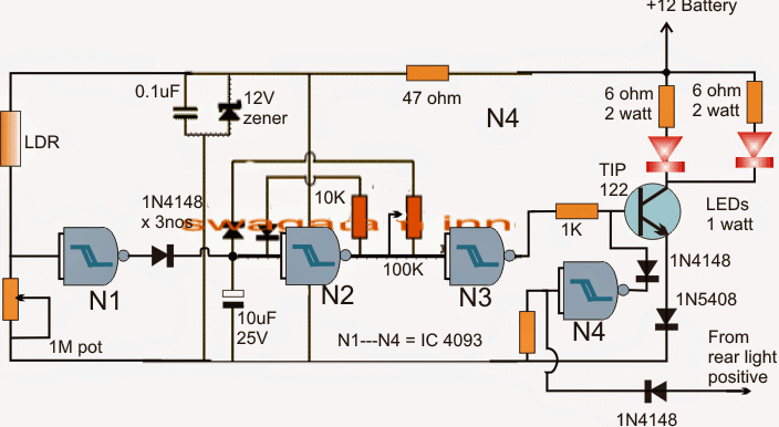
The requested darkness triggered car park light circuit can be made as per the above shown circuit details.

The entire circuit is build around a single IC 4093, the gates N1 to N4 are from this IC which are appropriately configured with the associated passive components.

N1 is wired as darkness sensor through the connected LDR across its input and ground. The pot determines the sensitivity control can be set for triggering N1 at the desired darkness level.

N2 is wired as a PWM control frequency generator stage, the associated pot can be used for setting the required degree of ON or OFF time to the LEDs and consequently control their average brightness and consumption.

N3 is used like a buffer, whose output is connected with the base of the driver transistor TIP122 which responds to the fed PWMs and drives the LEDs with the corresponding amount of brightness.

The gate N4 is positioned to stop the TIP122 conduction and the LED illumination whenever the tail lights are detected ON, meaning while the taillight bulbs are ON, the proposed darkness triggered park lights are shut off.

On the other hand, when a darkness is detected, N1 input is rendered negative which forces its output to go high, this high signal inhibits the oscillatory action of the N2, and causes its output to go low.

With N2 output is low, N3 output is accordingly prompted to go high, which in turn switches ON the TIP122 transistor and the LEDs.

This is held in the LED switched ON position (and flashing) until the darkness persists and dawn sets in, or/and the tail lights are switched  ON.

You'll also like:

  • 1.  How to Manufacture Automobile Electronic Parts and Earn a Handsome Income
  • 2.  Simple Car Shock Alarm Circuit
  • 3.  Simple Electronic Fuse Circuit
  • 4.  Simple Ignition Code Lock Circuit for Automobile Protection
  • 5.  Cell Phone Call Alert Security Circuit
  • 6.  Automotive Sensor Monitor Circuit Diagram

Filed Under: Automobile Electronics Tagged With: Darkness, Light, Park, Safety, Triggered

About Swagatam

I am an electronics engineer and doing practical hands-on work from more than 15 years now. Building real circuits, testing them and also making PCB layouts by myself. I really love doing all these things like inventing something new, designing electronics and also helping other people like hobby guys who want to make their own cool circuits at home.

And that is the main reason why I started this website homemade-circuits.com, to share different types of circuit ideas..

If you are having any kind of doubt or question related to circuits then just write down your question in the comment box below, I am like always checking, so I guarantee I will reply you for sure!

Previous Post: « Flashing Red, Green Railway Signal Lamp Circuit
Next Post: Free Energy Generator Circuit – The N-Machine »

Reader Interactions

Need Help? Please Leave a Comment! We value your input—Kindly keep it relevant to the above topic! Cancel reply

Your email address will not be published. Required fields are marked *

Primary Sidebar


Subscribe to New Posts

Categories

  • Arduino Projects (88)
  • Audio and Amplifier Projects (132)
  • Automation Projects (17)
  • Automobile Electronics (101)
  • Battery Charger Circuits (83)
  • Datasheets and Components (104)
  • Electronics Theory (143)
  • Free Energy (37)
  • Games and Sports Projects (11)
  • Grid and 3-Phase (19)
  • Health related Projects (25)
  • Home Electrical Circuits (12)
  • Indicator Circuits (14)
  • Inverter Circuits (88)
  • Lamps and Lights (142)
  • Meters and Testers (69)
  • Mini Projects (46)
  • Motor Controller (64)
  • Oscillator Circuits (27)
  • Pets and Pests (15)
  • Power Supply Circuits (108)
  • Remote Control Circuits (50)
  • Security and Alarm (64)
  • Sensors and Detectors (101)
  • Solar Controller Circuits (59)
  • Temperature Controllers (42)
  • Timer and Delay Relay (49)
  • Transmitter Circuits (29)
  • Voltage Control and Protection (37)
  • Water Controller (36)

Tags

Alarm Amplifier Application Arduino Automatic Battery Charger Circuits Control Controlled Controller Current Datasheet DC Detector Digital Driver Electronic Explained Explored Generator High Indicator Inverter Lamp LED Light Meter Motor Pinout Power Regulator Remote Sensor Simple Single Solar Supply Switch Timer Transistor Voltage Water Watt Working


Other Links

  • Privacy Policy
  • Cookie Policy
  • Disclaimer
  • Copyright
  • Videos
  • Sitemap


People also Search

555 Circuits | 741 Circuits | LM324 Circuits | LM338 Circuits | 4017 Circuits | Ultrasonic Projects | SMPS Projects | Christmas Projects | MOSFETs | Radio Circuits | Laser Circuits | PIR Projects |

Social Profiles

  • Twitter
  • YouTube
  • Instagram
  • Pinterest
  • My Facebook-Page
  • Quora
  • Stack Exchange
  • Linkedin


  • Recent Comments

    • Swagatam on Contact
    • Swagatam on Grid-tie Inverter (GTI) Circuit Using SCR
    • Swagatam on 10 Simple LED Chaser Circuit Diagrams Explained [Knight Rider, Scanner, Reverse-Forward, Cascaded]
    • Sparks on 10 Simple LED Chaser Circuit Diagrams Explained [Knight Rider, Scanner, Reverse-Forward, Cascaded]
    • Andrew on Grid-tie Inverter (GTI) Circuit Using SCR

    © 2025 · Swagatam Innovations