In this post I have explained a DC Motor controller which features a constant torque compensation for enabling the motor to run at a consistent speed irrespective of the load on it.
Drawback of Ordinary Speed Controllers
One drawback of the majority of simple speed controllers is they only provide the motor with a predetermined constant voltage. As a result the speed doesn't remain constant and varies with the load on the motor, due to absence of torque compensation.
For example in a model train, with simple controllers the speed of the train gradually decreases for the climbing gradients and accelerates while heading downhill.
Hence for model trains the pot control adjustment to keep up a selected motor speed likewise deviates depending on the load that the engine may be tugging.
The constant torque motor speed controller circuit I have explained in this article gets rid of this issue by tracking the motor speed and maintaining it constant for a predetermined control setting, no matter what the load may be on the motor.
The circuit can be applied in most of the models which uses a DC permanent magnet motor.
Calculating the Back EMF Factor
The voltage across the motor terminals comprises of a couple of factors, the back e.m.f. produced by the motor, and the voltage dropped across the armature resistance.
The back e.m.f. generated by the motor winding is normally proportional to the motor speed, which means that the motor speed could be monitored by measuring this back emf content. But, the main issue is to isolate and detect the back e.m.f. from the armature resistance voltage.
Supposing a separate resistor is attached in series with the motor then, considering that a common single current passes through this resistor and also through the armature resistance, the voltage drop across the two series resistors could well be equivalent to the drop across the armature resistance.
Actually, it can be assumed that when these two resistance values are identical then the two voltage magnitudes across each of the resistors will also be similar. With this data, it may be possible to deduct the voltage drop of R3 from the motor voltage, and get the required back e.m.f value for the processing.
Processing Back EMF for Constant Torque
The proposed circuit continuously monitors the back e.m.f. and accordingly regulates the motor current to ensure that, for an assigned pot control setting, the back e.m.f., along with the motor speed is maintained at a constant torque.
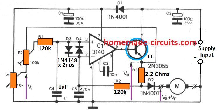
To be able to make the circuit description easier it is deemed that P2 is adjusted and held to its center position, and the resistor R3 is selected as an equivalent to the resistance value of the motor armature.
Calculating Motor Voltage
The motor voltage can be calculated by adding the back e.m.f. Va with the voltage dropped across the motor internal resistance Vr.
Considering that R3 drops a voltage Vr, the output voltage Vo will be equal to Va + 2 V.
The voltage at the inverting input (-) of IC1 will be Va + Vr, and that at non-inverting input (+) will be:
Vi + (Va + 2Vr - Vi) / 2
Since the above two voltage magnitudes are supposed to be equal, we organize the above equation as:
Va + Vr = Vi + (Va + 2Vr - Vi) / 2
Simplifying this equation provides Va = Vi.
The above equation indicates that the back e.m.f. of the motor is consistently held at the same level as the control voltage. This allows the motor to work with a constant speed and torque for any specified setting of the P1 speed adjustment.
P2 is included to compensate the difference level that may exist between the R3 resistance and the armature resistance. It executes this by adjusting the magnitude of positive feedback on the non-inverting input op amp.
The op amp LM3140 basically compares the voltage developed across the motor armature with the back emf equivalent across the motor and regulates the base potential of the T1 2N3055.
T1 being configured as an emitter follower regulates the speed of the motor in accordance with its base potential. It increases the voltage across the motor when a higher back emf is detected by the op amp, resulting in an increase in the motor speed, and vice versa.
T1 should be mounted over a suitable heatsink for proper functioning.
How to Set Up the Circuit
Setting up of the constant torque motor speed controller circuit is done by adjusting P2 with the motor with varying load until the motor achieves a constant torque regardless of the loading conditions.
When the circuit is applied for model trains, care must be taken not to turn P2 too much towards P1 which might result in the model train slowing down, and conversely P2 must not be turned too much in the opposite direction, which might result in the train speed actually getting faster while climbing an uphill gradient.

Comments
Hello Sir, I have a royobi elec. riding lawnmower and hit a rock that stopped the mower but it restarted and runs but the slightest load cuts it off. Those parts are expensive and I was hoping you might be able to help me know how to test if I need the motors or the slave controllers.
Hello Tony,
Is your lawnmower motor driven through an electronic circuit? If not then most probably the problem could be a mechanical problem.
Hello Sir,
yes it is a 48 volt system with two motors and controllers for the mower deck and another for the drive train which was not effected
Thank you Tony, for updating the info.
In that case you may have to isolate the effected motor from the driver circuit and check it separately by supplying a direct 48V DC to its wires. If you find the motor torque is good, that would confirm that the problem is with the controller circuit.
Hi swagatam,
I am building ebike using rewinded direct drive washing machine. I want to build my own controller, from what I read the best efficiency is from foc type controller. Foc monitor torque like your schematic, is this a kind of foc. Thanks.
Hi Wira,
You are right, FOC motor control (Field-Oriented Control) is a technique used to control the speed and torque of electric motors, particularly three-phase AC motors, with high precision and efficiency.
The above circuit is not a FOC controller circuit, FOC controller is much more complicated than this back EMF based controller.
Hello sir,
I am looking for a 24v dc motor controller for use with my 2 motors, 20a each motor. I need to control the speed of the motors but have good torque at lower speeds too.
I am trying to make a sort of go kart so these motors will be driving an old transmission.
I hope you can help instead of trusting china circuits that I could buy!!
Hello Kyle, 20 amp current looks too high. Unfortunately I don’t seem to have a constant torque motor controller circuit that can handle 20 amp current at this time. I am sorry about it.
Hello sir,
Thank you for looking! I appreciate your site and help, your explanations are very good!
Thank you so much Kyle, appreciate your feedback.
Hello!
Very good circuit Mr. Swagatam. I have tried it with a little DC motor and it works fine.
I`ve as well tried with a transistor triggered Pulse Motor but could not get it to run properly.
The current passing through was maximum 0.4 amps with 12 volts and thus it was spinning quite slowly. Normally without any pwm this pulse motor runs quite good with 2 amps.
What would be the recommended modification to the circuit to make it run at a higher amperage?
Cheers and thanx for the blog!
Thank you Fox, glad you tried the circuit and could make it work with a small motor. I can understand the circuit did not give proper results with a higher amp motor.
Basically, it’s the R3 resistor which is used a current sensing resistor, and this resistor value could be perhaps reduced for enabling the circuit to work with higher loads. You can try reducing the R3 value to some lower levels and check if that helps to generate more speed on your motor. P1 can be also tweaked simultaneously for increasing the speed.
I`ve tried with changing the R3 to lower numbers but I could not get so much of an improvement. The motor runs quite much the same, at very low speed.
Actually I am using an 741 op amp instead of the 3140 you proposed since it was easier to get. Might perhaps that be a factor for the low current?
Yes it could be due to low current from the transistor itself. I think the main issue is with the 2N3055 transistor. Either it needs to be modified into a Darlington transistor or replaced with a single Darlington device. You can convert it into a Darlington by adding another 2N2222 with the 2N3055 or simply replace the 2N3055 with a TIP142 transistor.
However I am not sure if a 741 could work in place of a 3140, I guess it should since an op amp is all that is required for this application.
If a Darlington is used for the transistor then it must include a base resistor, a 1K might be just enough.
Thanx for the Tips !
I have tried with a darington transistor with a 1k resistor at base and it got a little bit better. Now the current draws 1 amp Max. Although not yet working as I expect, since the aim is to make the motor for currents up to 7/8 amps. Btw, I`ve used 50 v 100 uF Capacitors instead 35 V from the circuit and 1N4007 Diodes instead of the 1N4001. IDK if that would have an impact on the current draw. I have as well noticed that even in the small DC motor the output voltage has a drop of almost 3 volts. With a 12V battery It draws max. 8.6 V in the output.
Any further modifications or recommendations?
The voltage rating of the capacitor simply indicates the maximum voltage tolerance of the capacitor beyond which it can explode. By increasing the voltage rating of the capacitor you have only helped it to increase its voltage tolerance level. The capacitor value must be ideally 1.5 times higher than the supply DC value of the circuit….so that has nothing to do with the working of the circuit or the motor. The voltage drop is probably because the transistor is configured as an emitter follower, which will itself drop around 1 V, and also because there’s a resistor in series with the motor.
Actually, the above design was take from an old electronic magazine, it is not my design so I am also finding it slightly difficult to improve its functionality.
BTW the series emitter resistor value must be equal to the internal resistance of the motor winding, I hope you have adjusted the resistor value accordingly.
Hi, thank you for you amazing work.
I have a little question, Im trying to build up a proyect but it is possible that at some point the load is going to be too big for the motor to continue spinning. How could i protect the motor from the higher current this will draw and what considerations should i take at the moment of chosing my power source?
Thank you.
Glad you liked my work, can you please specify the voltage rating of the motor, and whether it’s an AC or DC motor?
I’d like to use this circuit on a 12V wiper motor to be used as a power drive which could draw too much current for this circuit. (5A or more?) How could this circuit be modified for handling higher currents? Could you please add the wattage values of the resistors?
Thanks for wonderful practical useful articles.
I’ve just recently joined and receives all of your newsletters.
Hi, thank you, and glad you like the articles.
It is possible to increase the power handling capacity of the circuit by replacing the 2N3055 with a TIP35 and mounting it with a good heatsink.
All the resistors are 1/4 watt rated, except the 2.2 ohms, which can be a 5 watt resistor
Hi mr swag. I really love your project. Please how can i adjust this Constant Torque Motor Speed Controller Circuit for ac induction motor. Thanks
Hi prince, the above circuit cannot be used for ac induction motors, you can instead try the following concept:
https://www.homemade-circuits.com/how-to-make-versatile-closed-loop/
Thanks a lot. I will try it.
I have been using power tools such polishers, orbital wood grinders.
Having universal motors, High Speed-12000 rpm,230ac,2000watts
Built-in speed controller often not giving desired results, resulting into heavy commutation problem with rotor failure.
Request you suggest speed controller and provide me circuit.
Readily available scr/voltage dimmers are not effective
Awaiting your reply
Thanks
I think you can try the following concept:
https://www.homemade-circuits.com/how-to-make-versatile-closed-loop/
Thank you i will try it out
I want to try this on my cnc spindle dc motor,
Any suggestions for a 3amp circuit or changes you suggest?
You can use the same circuit without any changes, except R3, which could be reduced to 1 ohms or slightly lower.