In this post I will try to analyze what is constant current source and how it affects a load, or how it may be used with a load correctly for achieving the most efficient results.
The following discussion between me and Mr. Girish will clearly explain what is CC or how constant current operates.
How a Constant Current Source Works.
Question put by Mr. Girish.
I am trying to build a Arduino based Li-ion charger with a display, but I am with loads of confusions, if possible try to correct my puzzlement.
I have attached a diagram it is similar to which I am working with.
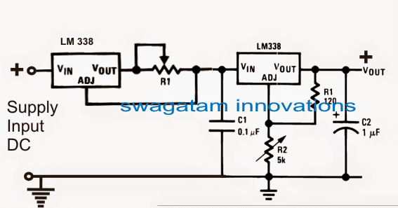
The LM317 in CC and CV mode, I have limited the voltage to 4.20V and current to 800mA (for 2AH battery) with 1.5ohm 1 watt resistor.
I am getting exactly 4.20V at output (open circuit) and short circuit current of exactly 0.80A.
But when I connect a Li-ion battery (with half charge which is old batteries from laptop) the current consumption is just 0.10A, and almost discharged battery not consuming not more than 0.20A.
If charging is done at this rate it might take 10 hrs or more for reaching full battery, which is not feasible.
Is it possible to force the current to flow through the battery at 0.80A rate?
As far as i know the batteries are in good condition.
Will the Current be Forced into the Load
My second question is: Does constant current source pump current into a load or is it just a maximum current limiter?
Answer
If you are supplying 4.2V and 800mA to a 3.7V/800mAH or to a 2AH cell, then everything is correct and nothing should be changed, because your charging specifications are perfect.
If the battery is not charging at the given full rate then the problem has to be with the battery not with the charging procedure.
You can try confirming the results with another meter if possible, to be entirely sure.
By the way a good battery should have accepted the 0.8 mAH charging rate and should have shown an immediate rise in its body temperature...if that is not happening then I guess the problem has to be with the battery.
You can also try another Li-ion battery and check whether it behaves in the same way or not. or you can try raising the current to full 1.5 amps, and check the response, but make sure to mount the ICs on a good heatsink, otherwise they will shut off.
Constant current source will not pump current, its job is is restricted to not to allow the load to consume current above the CC's specified value at any circumstances.
However ultimately it is the load which decides how much current it is supposed to consume. Current limiter will only work to stop the consumption if it reaches over the specified rating, and nothing more.
Feedback from Mr.Girish
Exactly, what I discovered too, but in YouTube, I have seen many people saying it "pumps" the current through the load.
They limited the current to 12.6 mA with 100 ohm resistor and I am getting short circuit current of around 12.6 mA, they connected number of LEDs in series and took reading, current flow remains the same 12.6mA. The input volt is hiked to 24V, but the LED remains without any harm.
link: www.youtube.com/watch?v= iuMngik0GR8
I too replicated the experiment and got the same result. I think this may look like current "pumping" but obviously not "pumping".
I think this video conclusion cannot be applied to Li-ion batteries, since LEDs are current driven devices.
In case of Li-ion battery, if we connect two in series we have to increase the voltage to 8.4V and not keeping the same voltage or unconditionally higher voltage as LEDs.
I am assuming that my batteries are faulty.
Answer:
In the video the person says a 1amp constant current source will push 1 amp to a 1 ohm and also to a 100 ohms regardless of the resistance value? it implies that it will do the same to a 1K resistor?? that's grossly incorrect...just try it with a 1K resistance.
You can apply Ohm's law and get the results quickly.
Constant current simply means that the source will never allow the load to consume more than the specified rating of the source, this is the ultimate truth for any constant current source.
It is the load that ultimately decides how much current it will consume.... provided the load V specs matches the source V specs.
This is the reason why we use different resistors with different LEDs, because resistors do resist current depending on their values.
It may be any kind of load, whether battery or LED or bulb or SMPS, as long as the V spec matches the source V spec, the current draw will be decided by the load.
The current source can do nothing but wait until the load tries to pull more than the rated value, and here the CC comes into action and stops the load from doing this.
Our mains input has around 50 amp current CC, does that mean it will push this current in our appliance, then we would see our appliances catching fire every now and then...;)
You can pump current by disturbing the voltage, that is by increasing the V beyond the load's V rating, which is technically wrong.
Feedback:
I too agree on this and I think the reason why LEDs able to lit without any harm at 24V because the current is limited to 12.6mA which would also affect the voltage (V and I are proportional and no voltage regulator in it).
Since the current is constant, the terminal LED voltage must also stay fairly constant. I done the same experiment and got 2.5 to 3V across the LED at 17V input.
Reply:
Yes that's another aspect, if the current is below the load's max current specs then the voltage will drop to the load's rated V specs, regardless of the input voltage increase, .....but not if the current is more than the loads rating, then it will burn the load.
That's why when we use a low current capacitive power supply, even though the input conversion produces 310VDC across the LED, it quickly drops to the connected LED's fwd drop value, because the current is limited by the low value capacitor which may be rated lower than the loads's max amp rating.
In the above indicated capacitive power supply, the output from the bridge is around 310V DC, but yet it is quickly dropped at the zener diode's value without burning the zener diode.
This happens because of low constant current from the capacitive supply which is unable to cause any harm to the zener diode, due to the much higher wattage of the zener diode.
Conclusion
From the above discussion we understand the following aspects regarding a constant current source:
- Constant Current Supply has only one job to do, stop the connected load from drawing more current than the input's CC rating.
- For example, a 7812 IC can be considered as a 1 amp 12V CC/CV regulator IC, because it will never allow the load to consume more than 1 amp and more tha 12V, regardless of the load rating.
- Alternatively, as long as the load's voltage rating matches the Constant current supply's Voltage rating, it will consume a current as per its own specification.
- Suppose we have a 12V supply with a 50 amp CC, and we connect a load rated at 12V 1 amp, so what will be the consumption of the load.
- It will be 1 amp strictly, because the load's V spec is correctly matched with the supply's V specs.
What happens if the supply V increases.
It will be then devastating for the load, as it will be forced to consume dangerous higher levels of current than its 1 amp rating, and finally it will burn.
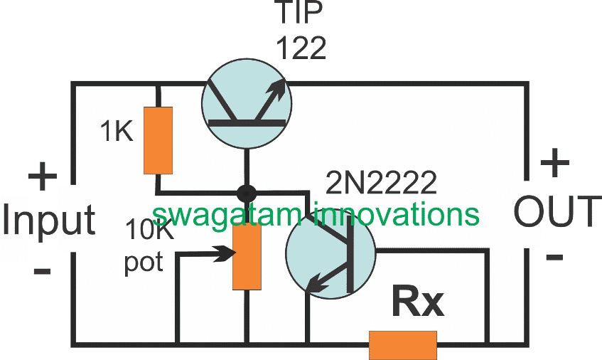
Simple Constant Current, Constant Voltage Circuit Using Transistors
The following image shows how a simple yet very reliable CC/CV regulator can be built using a couple of transistors or BJTs.
The 10K pot can be used for adjusting the required constant voltage output level, while Rx cab be set for fixing the constant current level at the output.
Rx may be calculated with the help of the following formula:
Rx = 0.7 / the Desired CC Level
Comments
I made a power supply with the IRFZ 44 Transistor. 0/ 50 V. Voltage is being adjusted but I want to adjust the current, I failed. I would be happy if you could help me. I would be grateful if you could send me a circuit drawing on this subject.
Sure, please check the circuits explained in the following article, and see how the BC547 and R2 are arranged for the current control:
https://www.homemade-circuits.com/0-300v-variable-voltage-current/
Hello Swagatam,
I have a Meanwell lrs-350-24 SMPS, which should give 15A, however when hooking up to my Li-ion battery pack BMS, SMPS goes into hiccup mode due to battery wanting more than 15A current.
Can I use the above circuit attached to the SMPS output to provide 10A constant current?
Rx would be 0.07Ohm correct? 2n2222 would have to be changed, maybe a 2N5038?
Many thanks,
Kyle
Hello Kyle,
Controlling the output current to 10 amps is definitely possible. However, I would recommend the MOSFET current controller version from the following article. The LOAD could be replaced with your battery terminals:
https://www.homemade-circuits.com/universal-high-watt-led-current-limiter/
Okay thank you!
So for that mosfet circuit, R1 is 1k and R2 can be calculated as such:
0.7/10 = 0.07Ohms.
Watts: 0.7×10 = 7Watt resistor
If I choose a larger mosfet (so it won’t heat up at 10A current) will I have to change T2 or any resistors?
Also the 15v zener, will I need to change that for 26v input?
Many thanks,
Kyle
Your calculations and assumptions are correct.
However for 26V input you can change the 1K value to 4k7 or 10K
T2 does not need to be changed as 4k7 or 10K collector load is quite big and acceptable for the transistor.
15V zener is only for protecting the MOSFET gate, it does not need any changes.
Perfect! Thank you for your help Swagatam!
You are welcome Kyle!
I see your simple CC/CV using the TIP 122. I’ve been looking for a CC circuit for charging a super capacitor off of a LiFePO4 battery at ~100amps @ 16.8VDC max(but more likely 14.5VDC). If I were to upsize this circuit and use something like a MJ11028G(x2) do you think that would be sufficient? Would Rx still be (0.7/100) for each circuit run in parallel? The circuit would be just to bring the capacitor(583F) voltage up safely to match the battery voltage and then a direct parallel circuit would take over.
Hope that isn’t too far off. My degree is in ME and power electronics has been a few years back.
(If you’re curious, I’m using this setup to crank a 7.3L diesel.)
Yes, using two MJ11028 in parallel to handle 50 amps is definitely possible. Even though the two transistors are rated to handle 100 amps but in real life they would not handle more than 50 amp even with the largest heatsink connected to them.
If you are connecting them in parallel, make sure to mount them over a single common large heatsink, one beside the other.
Rx would be still 0.7, but the lower transistor must now change to a TIP31. This can be also changed with TIP122, then 0.7 will become 1.4
The base resistor 1K can be calculated using the following formula:
(supply input – load voltage rating) x hFE / load current
Hello Sir,
I have a built a project which includes many transducers and sensors which are driven by two DC-DC Converters having output ratings of 24V, 50W and 5V, 50W.
I have a task to implement a circuit which senses the current drawn from these converters, an indication (LED) which shows that the current drawn is exceeding the threshold value (just as the CC mode of Regulated Power Supply) and if it does then it must immediately disconnect DC DC Converters from driving the sensors.
Please help me with the same.
Thank you!
Hello Pratham,
you can try the following concept with some modifications:
https://www.homemade-circuits.com/mains-over-load-protector-circuit-for/
1) replace the LED/LDR hand made opto coupler with any other ready made opto coupler
2) Replace the 220V input with converter input.
3) Connect the transducer to the relay output
4) Connect the +12V of the circuit with the converter DC supply
hi Mr…
1. i wish to build this circuit with single 3 watt led (Luxeon 3) on 220volt ac in every room… and also my citchen set.. so i hope this circuit could to make smaller size PCB and also cheapest cost exactly
2. if it possible what the value of resistor and wattage to change/Remove 10K VR because only will get fixed output 3,6 Volt 700mA.
3. could to change TIPP 122 with other ones (lowest cost transistor).
4. if you have i time, please share this circuit with PCB Layout with smaller size… i’m learning sprint layout software right now, it is difficult for me coz not auto route PCB
Hi Hilman, TIP122 is recommended for efficient current transfer, but you can try a TIP31 instead, and check if its works.
Please tell me the input voltage value for calculating the resistor values.
Rx = 0.6/LED current
input voltage is from accu 6v/7,2AH and li ion 18650 battery.
i don’t yet try transformerless PSU shown diagram above coz i assume max current will be no more than 100mA, and there is no stock TIP122 at store. i’m still looking for it at the other store
Here’s the formula for calculating resistor divider network
Vout = Vin.R2 / R1 + R2
Vout = 6R2 / 1000 + R2
4.5 = 6R2 / 1000 + R2
4.5(1000 + R2) = 6R2
4500 + 4.5R2 = 6R2
450 = 6R2 – 4.5R2 = 1.5R2
R2 = 4500/1.5 = 3000 ohms
3000 ohm will be the resistor which could be replaced with the shown 10K preset
Whats the max current that can be supplied using above ckt?
5 amp for the first circuit, if IC LM196 are used it becomes 10 amps max.
Ok,but won’t 10A require quite a high watt register.Are those available in market notmally?What about tip122/2n2222 ckt.That would also require high watt resistor I suppose.
yes for the first circuit if LM196 is used, the R1 could require a 10 watt resistor.
however in the the transistor based circuit the resistor value will be rather smaller, it could be around 0.6 x 10 = 6 watts
thanks now i understand
so according to what i understand is, once Rx is set say we want 2amps in the load so Rx will be 0.35 ohms, so the moment the current tries to exceed this cc range, the base of the 2n222 is triggered due to the voltage developed according to ohms law. am i right ? if yes, then the voltage across the base/emitter of the 2n222 will be at 0.7 at all values of threshold current, then it means 2n222 is always in the bias state which means tip122’s output will be zero, i’m somehow confused pls help
during an over current situation as soon as the 2N2222 triggers it switches OFF the TI122 which in turn removes the 0.7V potential from the 2N2222 base, and this allows TIP122 to conduct, this again causes an overload at the output triggering ON the 2N2222 and switching OFF TIP122…the cycle keeps repeating at an extremely rapid rate which ultimately attains a steady state wherein the load is allowed to operate with the average restricted amount of current.
Hi Swagatam,
I want to use the constant current circuit with 3.7v. 250MA Does it works? or if you have any other circuit to solve my purpose.
since i had used LM317 in Constant current configuration but it doesn’t work.
Thanks
Hi Ganesh, if you are referring to the first circuit, then yes it will definitely work for your application, and an LM317 circuit will also definitely work provided you calculate the resistor correctly.
remember there are many duplicate versions of the IC flooded in the market which may not work, so make sure you buy the original one….
Hi.
Im looking for timer for egg turner mechine.. 8hour interval and 3 seconds run. Can u make 6 pcs and supply. Please do call me on 8494915158.
Thanx
Asif
Do u know anybody who can supply these units.
sorry, I don’t know anyone else who can do this in my range
Hi, sorry, I won’t be able to provide practical samples…