• Skip to main content
  • Skip to primary sidebar

Homemade Circuit Projects

Need circuit help? Post them in the comments! I've answered over 50,000!

Blog | Categories | About | Contact | Calculators-online
You are here: Home / Datasheets and Components / Unijunction Transistor (UJT) 2N2646 Datasheet
ujt 2n2646

Unijunction Transistor (UJT) 2N2646 Datasheet

Last Updated on June 8, 2024 by Swagatam Leave a Comment

The 2N2646 is a type of Unijunction Transistor (UJT), which is commonly used in various oscillator based electronic circuit application.

Table of Contents
  • Pin Configuration:
  • General Characteristics:
  • Electrical Specifications:
  • Advantages and Disadvantages
  • Common Applications and Connections:

The following paragraphs provide the datasheet and the main specifications of the device:

Pin Configuration:

The following diagram shows the pinout configuration of the UJT 2N2646.

warning message: electricity is dangerous, proceed with caution
UJT 2N2646 pinout details
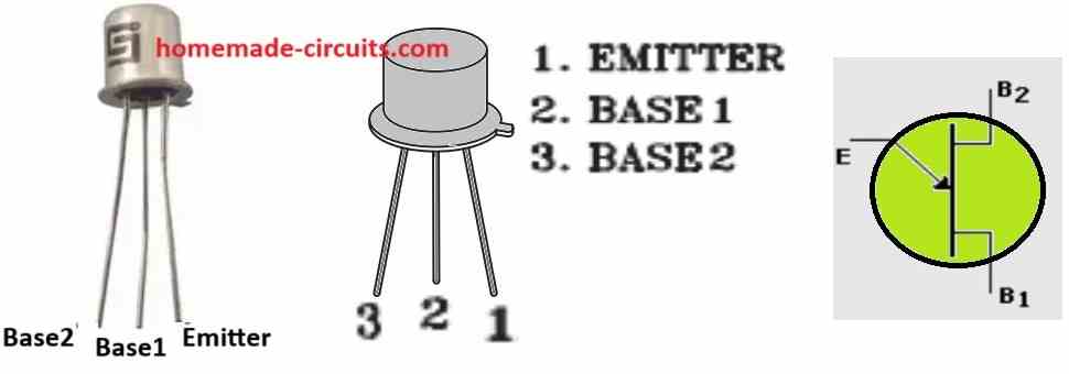
  • Pin 1 (Emitter): This pin is typically connected to the positive power supply voltage (Vcc).
  • Pin 2 (Base1): This is the control pin for the UJT. Its voltage determines the switching behavior of the device
  • Pin 3 (Base2): This pin is usually connected to ground or with a biasing resistor, towards ground.

General Characteristics:

  • Type: Unijunction Transistor (UJT)
  • Material: Silicon
  • Package: Typically TO-18 (although may vary, depending on manufacturer)
  • Number of Pins: 3 (Emitter, Base 1, Base 2)

Electrical Specifications:

  • Base Voltage (Vbb): 35V (maximum)
  • Emitter Reverse Voltage (Vbe): 30V (maximum)
  • Repetitive Peak Forward Current (If): 2A (maximum)
  • Peak Emitter Current (IE): 1 µA (maximum)
  • Valley Current (Iv): 6mA (typical)
  • Power Dissipation (Pd): 300mW (maximum)
  • Operating Temperature Range: 65°C to 125°C

Advantages and Disadvantages

  • Advantages: This UJT is easy to configure with minimum numberof external components. It is low cost. And good for triggering applications and requires low trigger current.
  • Disadvantages: The UJT may not be suitable for high-frequency applications, limited current handling capabilities.

Common Applications and Connections:

  1. Relaxation Oscillator

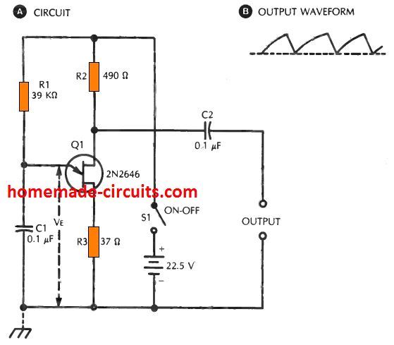
This is a popular application in which, the UJT generates a periodic output pulse train. Here's a basic setup:

  • Connect Base 1 (Pin 1) to the power supply (Vcc).
  • Connect a resistor (R1) between the Emitter (Pin 2) and the power supply.
  • Connect a capacitor (C1) between the Emitter (Pin 2) and ground.
  • Connect Base 2 (Pin 3) to ground.

The values of R1 and C1 determine the oscillation frequency. You can find online resources or circuit diagrams with specific component values for relaxation oscillators using the 2N2646.

  1. SCR Trigger Circuit:

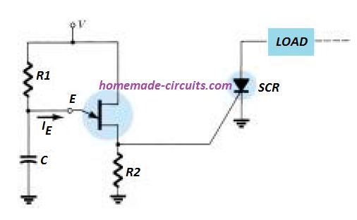
In this application, the UJT acts as a trigger for a Silicon Controlled Rectifier (SCR). The workingexplanation is given as follows:

  • The UJT acts as a voltage-controlled switch.
  • By applying a voltage pulse to the Emitter (Pin 2), you can trigger the UJT, which in turn triggers the SCR.

The specific connections will involve additional components, for example like resistors and SCR itself. You must Refer to SCR trigger circuit diagrams for detailed configurations.

References: Datasheet

You'll also like:

  • 1.  High Current Zener Diode Datasheet, Application Circuit
  • 2.  HX710B Air Pressure Sensor Datasheet, How to Connect
  • 3.  EGS002 Datasheet, Circuit Diagram Explained
  • 4.  Proximity Detector IC CS209A Pinouts – Datasheet Explained
  • 5.  IRF510 Datasheet [100V, 5.6 Amp, N-Channel MOSFET]
  • 6.  IRF540N MOSFET Pinout, Datasheet, Application Explained

Filed Under: Datasheets and Components Tagged With: 2N2646, Datasheet, Transistor, UJT, Unijunction

About Swagatam

I am an electronics engineer and doing practical hands-on work from more than 15 years now. Building real circuits, testing them and also making PCB layouts by myself. I really love doing all these things like inventing something new, designing electronics and also helping other people like hobby guys who want to make their own cool circuits at home.

And that is the main reason why I started this website homemade-circuits.com, to share different types of circuit ideas..

If you are having any kind of doubt or question related to circuits then just write down your question in the comment box below, I am like always checking, so I guarantee I will reply you for sure!

Previous Post: « IC LM358 Datasheet and Specifications
Next Post: Automatic Door Controller Circuit Diagram using a Single Push-Button »
Subscribe
Notify of
guest
guest
0 Comments
Inline Feedbacks
View all comments

Primary Sidebar

circuit simulator image

Subscribe to get New Circuits in your Email

Categories

  • Arduino Projects (90)
  • Audio and Amplifier Projects (132)
  • Automation Projects (17)
  • Automobile Electronics (101)
  • Battery Charger Circuits (83)
  • Datasheets and Components (105)
  • Electronics Theory (140)
  • Free Energy (37)
  • Games and Sports Projects (11)
  • Grid and 3-Phase (19)
  • Health related Projects (25)
  • Home Electrical Circuits (12)
  • Indicator Circuits (15)
  • Inverter Circuits (89)
  • Lamps and Lights (142)
  • Meters and Testers (71)
  • Mini Projects (46)
  • Motor Controller (64)
  • Oscillator Circuits (28)
  • Pets and Pests (15)
  • Power Supply Circuits (89)
  • Remote Control Circuits (50)
  • Security and Alarm (64)
  • Sensors and Detectors (103)
  • SMPS and Converters (29)
  • Solar Controller Circuits (59)
  • Temperature Controllers (42)
  • Timer and Delay Relay (49)
  • Transmitter Circuits (29)
  • Voltage Control and Protection (38)
  • Water Controller (36)

Other Links

  • Privacy Policy
  • Cookie Policy
  • Disclaimer
  • Copyright
  • Videos
  • Sitemap

People also Search

555 Circuits | 741 Circuits | LM324 Circuits | LM338 Circuits | 4017 Circuits | Ultrasonic Projects | SMPS Projects | Christmas Projects | MOSFETs | Radio Circuits | Laser Circuits | PIR Projects |

Social Profiles

  • Twitter
  • YouTube
  • Instagram
  • Pinterest
  • My Facebook-Page
  • Quora
  • Stack Exchange
  • Linkedin
  • Recent Comments

    • Swagatam on How to Convert a Low Power Inverter to a High Power Inverter
    • Swagatam on Simple Buck Converter Circuits using Transistors
    • NGANG on How to Convert a Low Power Inverter to a High Power Inverter
    • Swagatam on Make this 7 Segment Digital Clock with Beep Alert Circuit
    • Swagatam on Make this 7 Segment Digital Clock with Beep Alert Circuit

    © 2025 · Swagatam Innovations