Nowadays the CFL and fluorescent lamps are almost completely replaced with LED lamps, which are mostly in the form of circular or square shaped flat ceiling mounted LED lamps.
These lamps beautifully merge with the flat ceiling surface of our homes, offices or shops providing an aesthetic look for the lights, along with a high efficiency output, in terms of power saving and space illumination.
In this article I have explained a simple mains operated buck converter which can be used as a driver for illuminating ceiling LED lamps between 3 watt and 10 watt range .
The circuit is actually a 220 V to 15 V SMPS circuit but since it is a non-isolated design it gets rid of the complex ferrite transformer and the involved critical factors.
Although a non-isolated design does not provide isolation to the circuit from mains AC, a simple rigid plastic cover over the unit easily counters this drawback, guaranteeing absolutely no threat to the user.
On the other hand, the best things about a non-isolated driver circuit is that, it is cheap, easy to build, install and use, due to the absence of a critical SMPS transformer, which is replaced by a simple inductor.
The use of a single IC VIPer22A by ST microelectronics makes the design virtually damage proof, and permanent, provided the input AC supply is within the specified 100 V and 285 V range.
About the IC VIPer22A-E
The VIPer12A-E and the VIPer22A-E that happen to be a pin-for-pin match, and are designed for numerous mains AC to DC power supply applications. This document presents an off-line, nonisolated SMPS LED driver power supply using the VIPer12/22A-E.
Four unique driver designs are included here. The chip VIPer12A-E can be used for driving 12 V at 200 mA and 16 V 200 mA ceiling LED lamps.
The VIPer22A-E can be applied for higher wattage ceilng lamps arted with 12 V/350 mA and 16 V /350 mA supplies.
The same PCB layout could be employed for any output voltage from 10 V to 35 V. This makes the application hugely diverse, and suitable for powering a wide range of LED lamps, from 1 watt to 12 watt.
In the schematic, for loads less which can work with less than 16 V, diode D6 and C4 are included, for loads requiring over 16 V, diode D6 and capacitor C4 are simply removed.
How the Circuit Works
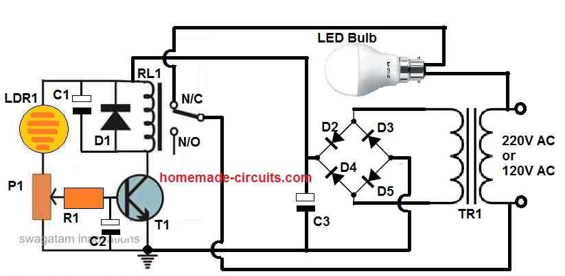
The circuit functions for all the 4 variants are essentially identical. The variation is in the startup circuit stage. We have explained Model as illustrated in the Figure 3.
The converter design output is not isolated from the mains AC 220V input. This causes the AC neutral line to be common to the output ground of the DC line, hence providing a back reference connection to the mains neutral.
This LED buck converter costs less because it does not depend upon the traditional ferrite E-core based transformer and the isolated opto coupler.
The mains AC line is applied via diode D1 which rectifies the alternate AC half cycles to a DC output. C1, L0, C2 constitute a pie-filter {to help} minimize EMI noise.
The value of the filter capacitor is selected to manage an acceptable pulse valley, since the capacitors get charged each alternate half cycle. A couple of diodes can be applied instead of D1 to endure ripple burst pulses of up to 2 kV.
R10 satisfies a couple of objectives, one is for restricting inrush surge and the other is to work as a fuse in case there is a catastrophic malfunction. A wire wound resistor deals with the inrush current.
Fire resistant resistor and a fuse works extremely well according to system and security specifications.
C7 controls the EMI by leveling line and neutral disturbance without needing the Xcap. This ceiling LED driver will certainly comply with and pass the EN55022 level "B" specifications. If the load demand is lower, then this C7 could be omitted from the circuit.
The voltage developed inside C2 is applied to the IC's MOSFET drain through pins 5 to 8 connected together.
Internally, the IC VIPer has a constant current source that provides 1mA to the Vdd pin 4. This 1 mA current is used to charge the capacitor C3.
As soon as the voltage on the Vdd pin extends to a minimal value of 14.5 V, the IC's internal current source switches off and the VIPer begins triggering ON/OFF.
While in this situation, the power is delivered through the Vdd cap. The electricity stored inside this capacitor has to be higher than the power necessary to provide the output load current together with power to charge of the output capacitor, before the Vdd cap drops below 9 V.
This could be noticed in given circuit schematics. The capacitor value is thus selected to support the initial switch ON time.
When a short circuit happens, the charge inside Vdd cap drops lower than the minimum value allowing the ICs built in high voltage current generator to trigger a fresh startup cycle.
The capacitor's charging and discharging phases decide the period of time that the power supply will be switched on and off. This decreases the RMS warming impact on all parts.
The circuit that regulates this includes Dz, C4 and D8. D8 charges C4 to its peak value throughout the cycling period while D5 is in the conduction mode.
During this period, the supply source or reference voltage to the IC is reduced by the forward voltage drop of a diode below the ground level, that makes up for the D8 drop.
Therefore primarily the Zener voltage is equivalent to the output voltage. C4 is attached over Vfb and the supply source to smoothen the regulation voltage.
Dz is a 12 V, 1⁄2 W Zener having a particular test current rating of 5 mA. These Zeners that are rated at a smaller current provide higher precision of the output voltage.
In case the output voltage is below 16 V, the circuit could be set up as shown in Figure 3, where Vdd is isolated from the Vfb pin. As soon as the IC's built in current source charges the Vdd capacitor, Vdd can attain 16V at the worse circumstances.
A 16 V Zener having a 5% minimal tolerance could be 15.2 V in addition to the built in resistance to ground is 1.230k Ω that generates an extra 1.23 V to give an overall of 16.4 V.
For 16 V output and bigger, the Vdd pin and the Vfb pin can be allowed to promote a common diode and capacitor filter exactly as indicated in Figure 4.
Inductor selection
At the inductor's starting up operating stage in the discontinuous mode could be determined through the below given formula which provides an effective estimation for the inductor.
L = 2 [ Pout / (Idpeak)2 x f) ]
Where Idpeak is the lowest maximum drain current, 320 mA for the IC VIPer12A-E and 560 mA for the VIPer22A-E, f denotes the switching frequency at 60 kHz.
The highest peak current controls the power supplied within the buck converter configuration. As a result, the above given calculation looks suitable for an inductor designed to work in discontinuous mode.
When the input current slips down to zero, then the output peak current gets two times the output.
This restricts the output current to 280 mA for the IC VIPer22A-E.
In case the inductor has a bigger value, switching between continuous and discontinuous mode, we are able to achieve 200 mA easily far from the current restriction issue. C6 needs to be a minimal ESR capacitor to achieve the low ripple voltage.
Vripple = Iripple x Cesr
D5 requires to be a high speed switching diode, but D6 and D8 can be ordinary rectifier diodes.
DZ1 is employed to fix the output voltage to 16 V. The characteristics of the buck converter causes it to charge-up at the peak point with no-load condition. It is advised to use a Zener diode that's 3 to 4 V greater than the output voltage.
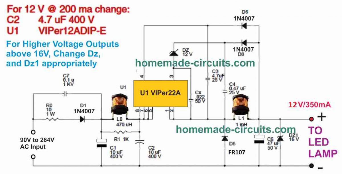
Figure 3 above shows the circuit diagram for the ceiling LED lamp prototype design. It is designed for 12 V LED lamps having a optimum current of 350 mA.
In case a lesser amount of current is desirable, then the VIPer22A-E could be transformed into a VIPer12A-E and capacitor C2 could be lowered from 10 μf to 4.7 μF. This gives as much as 200 mA.
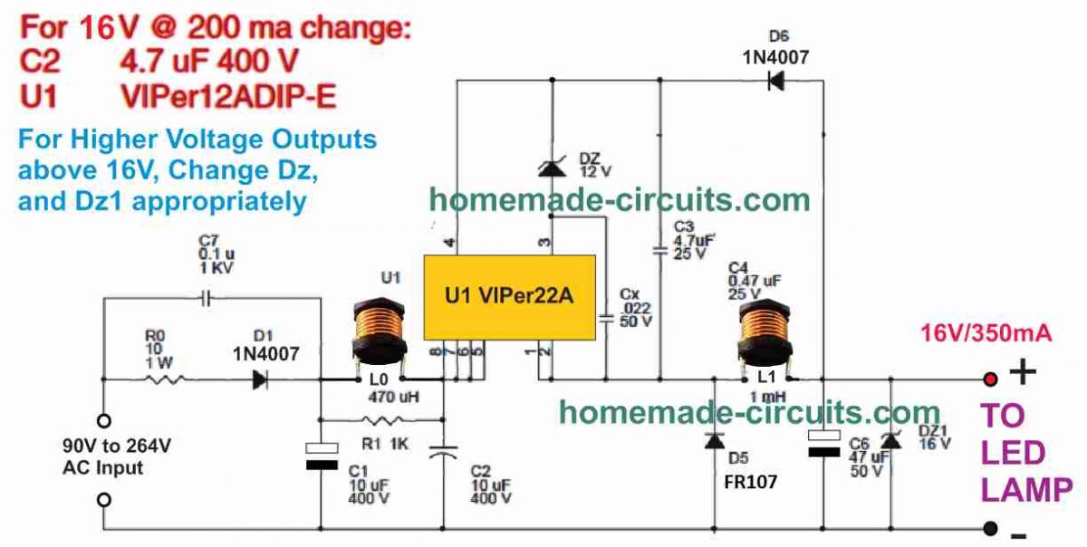
Figure 4 above demonstrates the identical design except for 16 V output or more, D6 and C4 could be omitted. The jumper connects the output voltage with the Vdd pin.
Layout ideas and Suggestions
The L value provides the threshold limits between continuous and discontinuous mode for a specified output current. To be able to function in discontinuous mode, the value of the inductor must be smaller than:
L = 1/2 x R x T x (1 - D)
Where R indicates the load resistance, T denotes the switching period, and D gives the duty cycle. You will find a couple of factors to take into account.
The first is, the greater the discontinuous the larger the maximum current. This level must be held below the minimal pulse by pulse current control of the VIPer22A-E that is 0.56 A.
The other is when we work with a bigger sized inductor to operate constantly, we encounter surplus heat due to switching deficits of the MOSFET within the VIPer IC.
Inductor Specifications
Needless to say, the inductor current specification should be more than the output current to avoid the chance of saturating the inductor core.
Inductor L0 can be built by winding 24 SWG super enameled copper wire over suitable ferrite core, until the inductance value of 470 uH is achieved.
Likewise, the inductor L1 could be built by winding 21 SWG super enameled copper wire over any suitable ferrite core, until the inductance value of 1 mH is achieved.
Complete Parts List
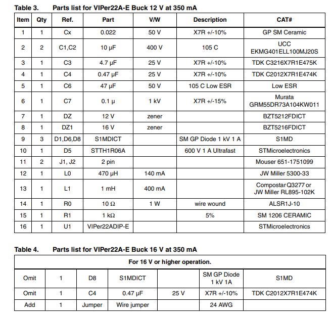
For more details and PCB design please refer to thisComplete Datasheet


Comments
Thanks Mr swag for this post but is there any version of the driver circuit that can drive 2 /3colour led combination such that if the mains supply switch is toggled on and off it changes to a separate color combination thank you
Thanks nnaji for your feedback, if possible I will try to update the same.
WHAT ABOUT A 48 VOLTS CIRCUIT?